ATI Q46 Modbus Communications Manual
7
O&M Manual
Rev-D (2/16)
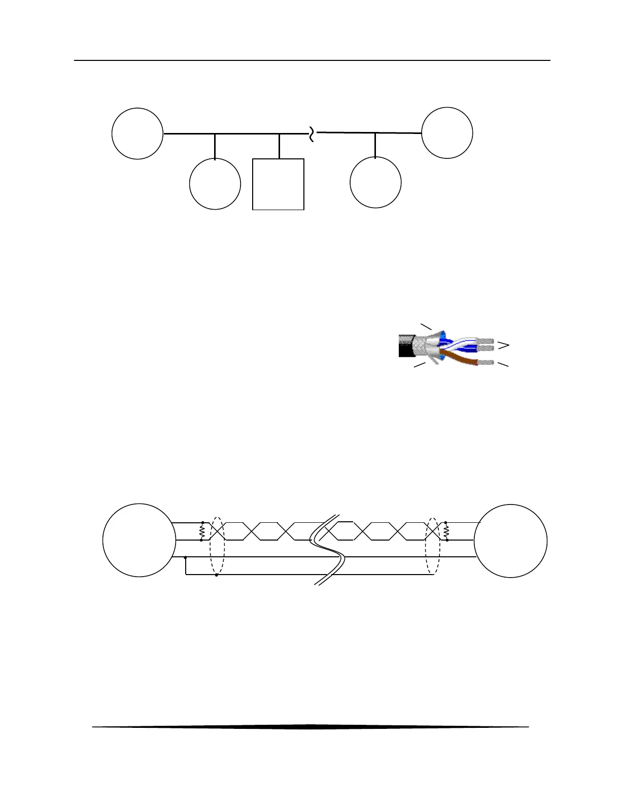
The master node may be located anywhere on the network, not just at one end.
1.5 Cable Specification
The bus is a cable composed of a twisted pair of wires with a characteristic impedance of 120
ohms, and a 120-ohm termination resistor connecting the pair of wires at each end. Several
manufacturers offer cables specifically designed for RS485, such as Belden’s 3106A, which
features one twisted pair, a separate signal common, a
foil shield, and a drain wire in contact with the shield.
The twisted pair, labeled A and B (or – and +, respectively), form a differential transmission line
capable of operating over a common mode voltage range from –7v to +12v
(note 2)
. That is, the
ground potential at each end of the network may differ by this amount. Connecting a signal
common to each slave device will keep this potential to a minimum. The shield around the
conductors provides protection from EMI (electromagnetic interference) and should be connected
to common or ground at only one point to avoid circulating currents that might actually generate
interference on the inner conductors. A schematic of the bus is shown below.
Device
1
Device
2
Master

 Loading...