www.atkinsonelectronics.com Circuit Board Division
800.261.3602 Revised 05/19
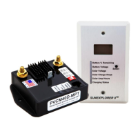
New Installation Instructions for PVCM40D-MPT
1. Complete the installation of the solar panels following the solar panel manufacturer’s instructions for
panel mounting and wire size based on total wattage of the solar panels and the distance between
panels and batteries. If the distance is less than 15 feet and the total solar panel charge Amps is 40
Amps or less, 8 AWG wire or larger is recommended. If the distance is greater than 15 feet use a 6
AWG wire. Reference the wire size recommendation chart.
2. Complete the installation of the optional display module and cat5e cable run to the charge
controller’s mounting location.
3. Identify the polarity (positive and negative) on the wires used for the battery and solar panels. Wire
the PVCM according to the wiring diagram (page 12). Keep the solar panels covered with an opaque
material until wiring and setup is complete.
4. Choose a location for the controller that is close to the battery location to minimize the voltage drop
when charging. The recommended location should be away from moisture and heat sources and
protected from weather.
5. Mount the PVCM controller in or next to the battery box for temperature compensation routines to
work properly using two ½ inch # 10 wood or sheet metal screws. Remove the fuse from the fuse
holder.
6. The red and black wires used to connect to the battery should wire directly to the controller using
proper ring terminal connectors.
7. Connect the positive wire from the solar panels to the PV connection on the controller, and connect
the panel’s negative wire to the battery negative terminal. Set the Battery type DIP switch for your
battery type. See diagram showing the switches and the four battery type settings.
8. Review all your wire connections to avoid any reverse polarity connections before re-installing the
fuse.
5