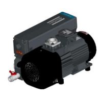
Figure 38 Motor coupling half position - GVS 100A
1. Mounted on the motor shaft end 2. Stroke limit on the rotor's bushing
3. Torque for press screw: 2 Nm (for
M5 screw), 16 Nm (for M8 screw)*
4. M8 X 30 Q8.8 (4 quantity)
5. M8 X 20 Q8.8 (4 quantity)
6. M8 X 30 Q8.8 (1 quantity)
1. Mounted on the motor shaft end 2. Stroke limit on the rotor's bushing
3. Torque for press screw: 2 Nm (for
M5 screw), 16 Nm (for M8 screw)*
4. M8 X 30 Q8.8 (4 quantity)
5. M8 X 20 Q8.8 (4 quantity)
6. M8 X 30 Q8.8 (1 quantity)
* Glued with LOCTITE 243
12/2021 - ©Atlas CopcoPage 596996022430_C
Installation
 Loading...