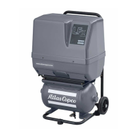
An optional wheel set and handle set for the 50 litre (13 US gal/11 Imp gal/1.75 cu. ft) and 90 litre (23.7
US gal/19.8 Imp gal/3.15 cu. ft) air receivers.
• Galvanized air receiver
An optional air receiver for extra corrosion protection.
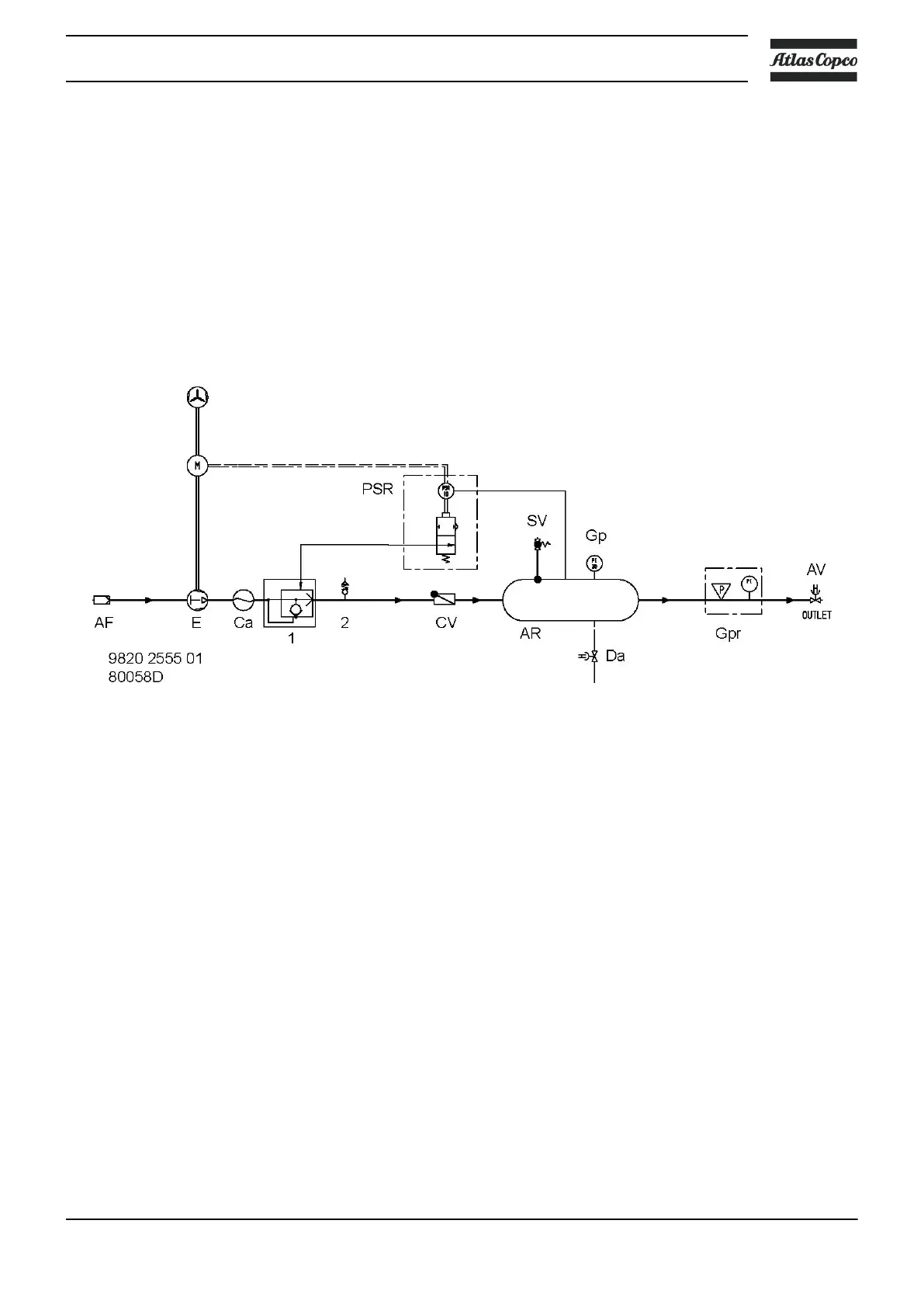
2.2 Flow diagrams
LFx Trolley and Complete unit on air receiver
Flow diagram
When the ON/OFF switch is put to position ON and the pressure in the air receiver is low enough, pressure
switch (PR) starts the motor.
On single-phase LFx 1.5 and LFx 2.0 units a vent valve (2) ensures smooth start-up.
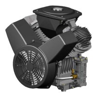
Air drawn through filter (AF) into compressor element (E) is compressed. The air is cooled in air cooler (Ca)
and enters air receiver (AR) through check valve (CV). The air is discharged through the pressure regulator
(Gpr).
When the pressure in the air receiver reaches the upper limit, pressure switch (PR) stops the motor.
On LFx 1.5 and LFx 2.0 units a quick blow-off valve (1) blows off the air between element (E) and check
valve (CV) and ensures smooth stopping.
The air receiver is equipped with a manual drain (Da) for draining the condensate after stopping.
Instruction book
2920 7002 03 13
 Loading...