2920 1257 04
4
Instruction book
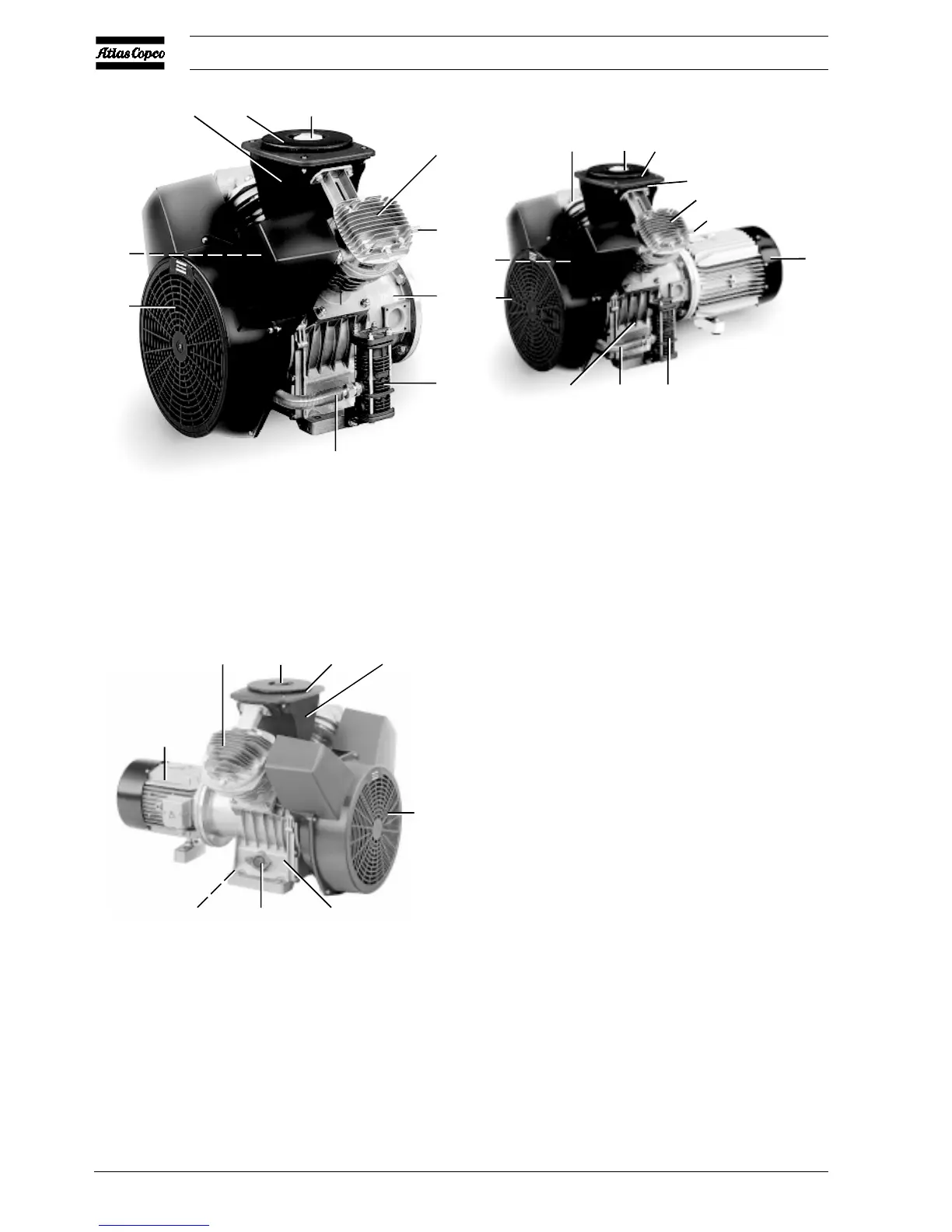
Fig. 1.1 Example of Compressor Block with unloading
valve
Fig. 1.2 Example of Power Pack with unloading valve
Fig. 1.3 Example of Power Pack
AF Air filter
DP Oil drain plug
FN Fan
M Motor
SG Oil level sight-glass
1 Cover
2 Intercooler
3 Air inlet silencer
4 Crankcase
5 Cooling pipe
6 Cylinder
7 Unloader
8 Relief valve
9 HP cylinder
10 LP cylinder
Figs. 1.1 up to 1.3 General views, Compressor Block -
Power Pack
When the pressure in the air receiver reaches the pre-set
maximum pressure, the contacts as well as pressure release
valve (2) are opened. The motor stops, the air at the delivery
side of the compressor is vented to atmosphere and check valve
(CV) closes to prevent venting of the receiver.
When the pressure in the air receiver decreases to the pre-set
minimum pressure, the contacts of the air pressure switch close
and pressure release valve (2) closes. The motor restarts and
compressed air is supplied to the receiver again.
3AF 1
6
8
4
7
5
FN
2
50948F
45
7
FN
2
10
1
AF
3
9
8
M
50949F
M
10 1
AF
3
FN
DP
SG
4
50973F
 Loading...