2920 1443 01
4
Instruction book
Rotor
The sections of drying material are wrapped onto a core and
contained in a jacket. The power of the motor is transmitted to
the rotor, through a pin-type coupling, a worm gear and a drive
shaft.
A lip-seal (29-Fig. 1.4), fitted on the rotor jacket, separates the
wet and dry sides of the rotor. The lip of the seal rests on the
surface of a ring clamped between the flanges of the vessel.
Sealing sectors
Both end faces of the rotor are provided with a sealing sector
for conducting the regeneration and cooling air flows through
the rotor. The sector on the regeneration air inlet is spring-
loaded. Both sectors slide on an inner and an outer ring fixed to
the rotor. A slight clearance is left between the faces of the
sectors and the rotor end faces.
The regeneration air inlet sealing sector covers a segment of 90
degrees of the dry side rotor face and is provided with a filter.
The outlet sealing sector is bigger, as it also accommodates the
cooling sector.
An Electronic Water Drain (EWD) is connected to the lower
part of the regeneration air compartment of the dryer.
Electrical control
The operation of the rotor motor is controlled by the electric
regulator of the compressor.
By-pass system
The dryers are standard equipped with a by-pass system
including an air inlet valve, an air outlet valve and a by-pass
valve. A regeneration air shut-off valve and a connection pipe
set is also included in the dryer package. A safety valve may
also be fitted.
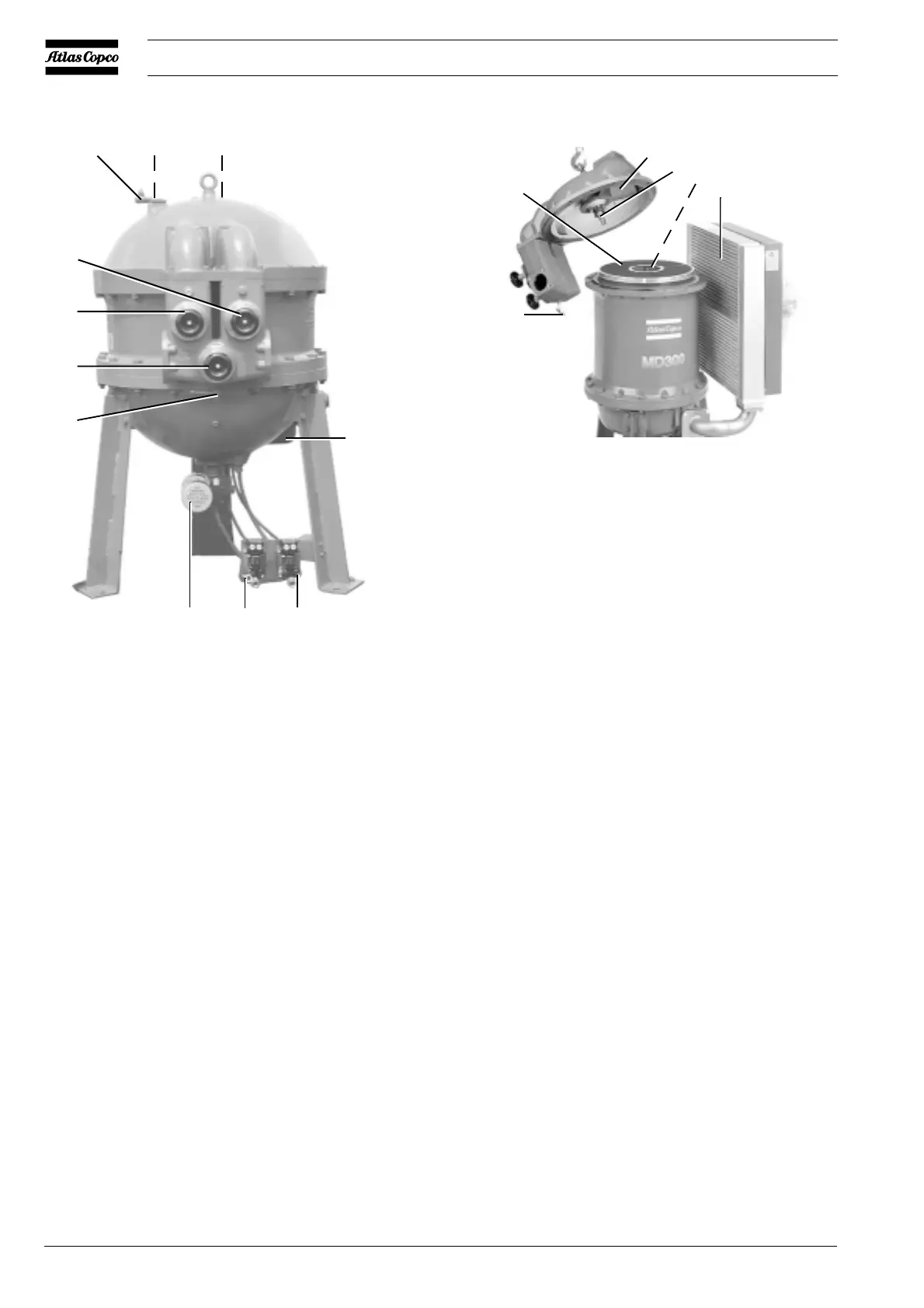
1 Valve for (-) connection, pressure differential gauge
2 Valve for (+) connection, pressure differential gauge
3 Throttle valve
4 Regeneration air cooler
5 Electronic Water Drain, inlet air water separator
6 Electronic Water Drain, regeneration air water separator
7 Rotor motor with incorporated gearbox
8 Manual drain valve, dryer inlet water separator
9 By-pass valve
10 Air outlet valve
11 Air inlet valve
Fig. 1.2 General view of MD600 W
1 Regeneration air sector
2 Nozzle
3 Ejector
4 Regeneration air cooler
5 Manual drain valve, dryer inlet water separator
6 Rotor
Fig. 1.3 Inside view of MD300
7
6
5
1
23
4
11
10
9
8
51337F
1
2
3
4
5
6
51338F
 Loading...