2920 1443 01
8
Instruction book
1.4 Electrical system
The motor must be wired to the electrical equipment of the
compressor as shown on the relevant circuit diagram.
1.4.1 MD400/800/1300/2500 W VSD (Figs. 1.13 up
to 1.15)
The worm gear motor must be connected to the frequency
converter for the dryer (A21) in the electrical cabinet of the
compressor. The rotor speed of the dryer depends on the speed
of the compressor motor. When the compressor runs at
maximum speed, the dryer will also run at maximum speed and
vice versa. The dryer motor stops when the compressor runs
unloaded.
1.4.2 All other MD dryers (Figs. 1.9 up to 1.12)
The worm gear motor (M40) is connected in the circuit of the
compressor air pressure switch or, in case of an Elektronikon-
controlled compressor, in series with a contact of the loading/
unloading relay. Thus the worm gear motor stops running when
the compressor is unloaded. This condition is required since
hot compressed air for regenerating the rotor is not available
when the compressor runs unloaded.
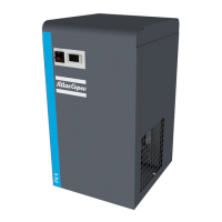
Fig. 1.6 Drain frequency during alarm condition
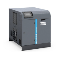
Fig. 1.7 Control panel
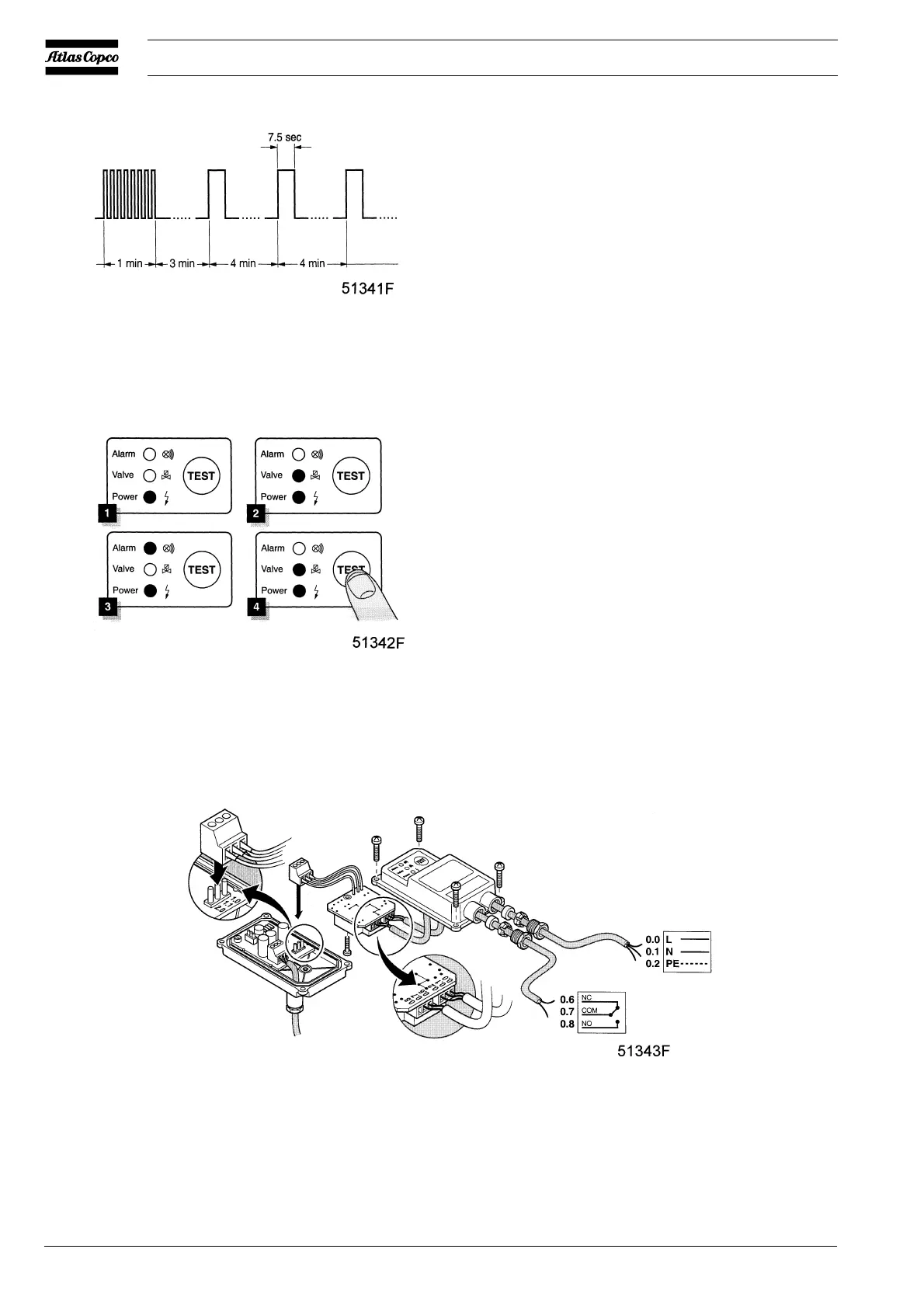
0.0 Line terminal
0.1 Neutral terminal
0.2 Earth terminal
0.6 Normally closed terminal
0.7 Common terminal
0.8 Normally open terminal
Fig. 1.8 Electrical connections
 Loading...