12
PAGE
Repair Instructions No.181.03/98
PHE 6 H / PHE 6 S
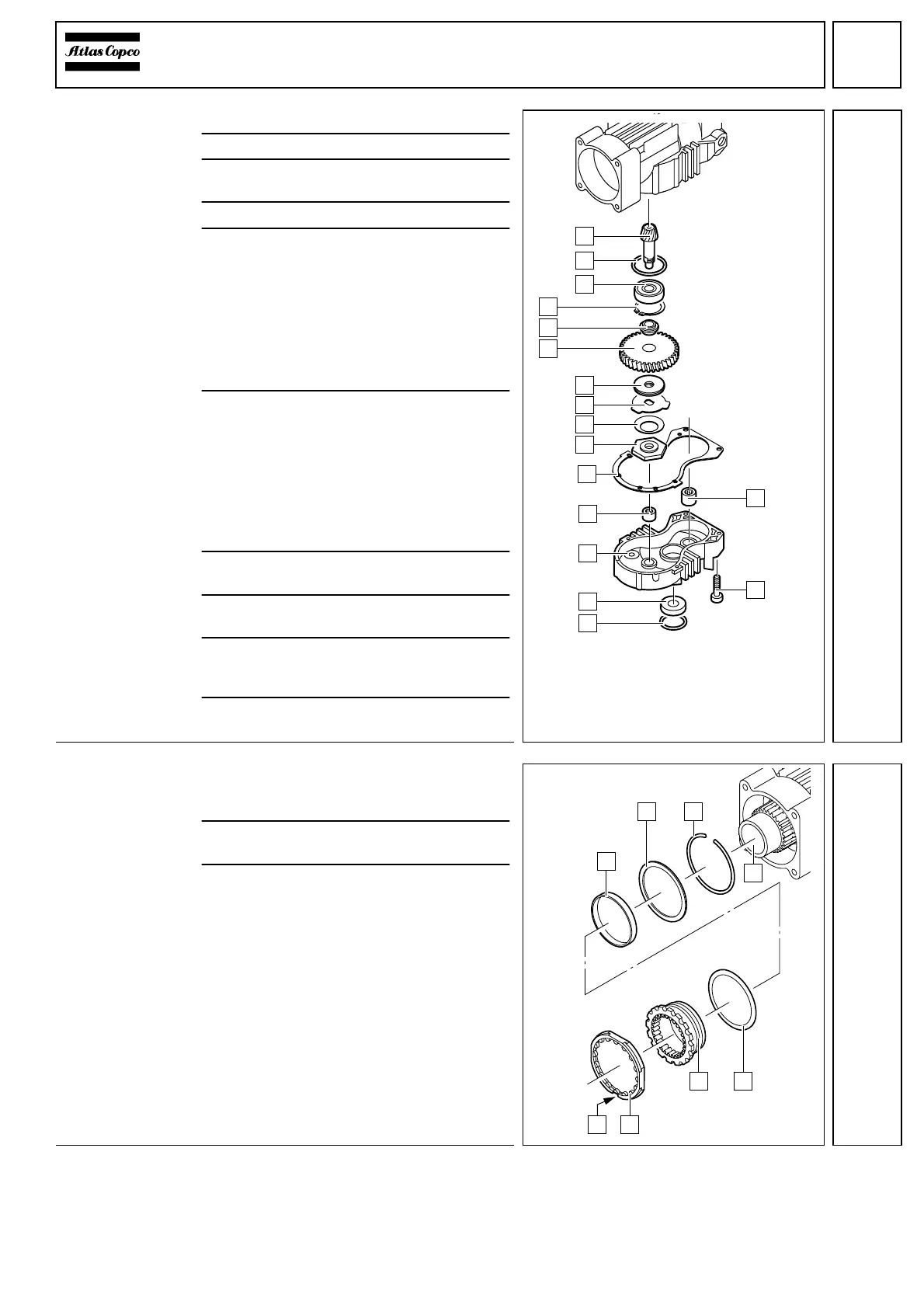
Mounting the
reduction
gear shaft
1 Insert the O-ring (E) into the housing.
2 Press the bearing (D) onto the pinion (F).
3 Press the pinion (F) with the bearing (D)
into the housing.
4 Insert the spring ring (C).
5 Push the following parts over the pin-
ion (F):
- clutch (B),
- drive (A),
- friction disk (9) (the covering must face
- the drive),
- securing plate (8) ,and
- cup spring (7) (the bulging must face
- the clutch).
6 Block the drive (A) against twisting and
screw down the clutch (6) as follows:
Apply a torque wrench with a 32 mm nut to
the clutch (6) with pressure such that the
resilience is overcome. Screw down the
clutch (6).
☞
Torque 3 Nm, use screw locking de-
vice.
7 Bend the three lugs of the securing
plate (8) in order to secure the clutch (6).
8 Press the needle bearings (4) and (G) into
the gear box cover (3).
9 Fit the gear box cover (3) with the
gasket (5) to the housing and fasten it with
the six screws (H).
10Insert the O-ring (1) and the seal (2) into
the housing.
PHE 6 S:
Mounting the
rotary stop
1 Fit the rings (4 and 2) and the spacer (1)
to the sleeve (5) and secure it with the
spring ring (3).
2 Push the sleeve (5) over the cylinder (7)
inside the housing.
3 Fit the locking ring (6) to the sleeve (5) in-
side the housing (mind the right position!)
and insert them as far as they will go with
aid of a suitable mandrel.
☞
The relief (7) of the locking ring (6) for
the switch must face down (see illus-
tration).
F
A
B
C
D
E
9
8
7
6
5
G
4
3
2
1
H
1
6
5 4
32
7
7
 Loading...