Do you have a question about the Atlas Copco PHE 3 and is the answer not in the manual?
Steps to remove the carbon brushes and associated parts from the tool.
Procedure for dismantling the SDS-Plus reception mechanism, applicable for PHE 3.
Steps for dismantling the FIXTEC reception system, specific to PHE 3 X models.
Instructions for removing the main gear housing assembly from the tool.
Detailed steps to safely remove the spindle component from the tool.
Procedure to detach the striker component using a mandril.
Steps to dismantle the spindle, focusing on the outer components and retaining clip.
Methods for removing the inner locking ring of the spindle, varying by manufacture date.
Specific steps for dismantling inner spindle parts for the PHE 3 model.
Specific steps for dismantling inner spindle parts for the PHE 3 X model.
Procedure to remove the back gear shaft and the cylinder assembly.
Steps for dismantling the back gear shaft, including parts like tumble drive and washer.
Instructions for removing the angle drive and associated washers.
Steps to remove the motor cover, noting potential glued rubber cap.
Procedure for dismantling the tool handle, including buffer and locking ring.
Steps to remove electrical components like switch, capacitor, and triac.
Procedure to remove the motor unit from the tool housing.
Steps for removing the armature and associated parts like toothed wheel and bearing.
Steps to remove the field component, including deflector plate and buffer.
Recommendations for regular tool maintenance and part exchange.
Table detailing torque values for various screws during assembly/disassembly.
Instructions for cleaning parts and performing an abrasion check.
Requirement for electrical testing before re-assembly.
Detailed chart and instructions for lubricating tool parts during maintenance.
Steps for mounting the field component into the field housing.
Procedures for assembling and mounting the armature onto the shaft.
Steps for mounting the motor into the main motor housing.
Steps for connecting and assembling electrical components into the handle.
Procedure for mounting the handle, including buffer, cover, and securing bolts.
Steps for fitting and securing the motor cover with screws.
Procedure for assembling and inserting the angle drive with washers and locking ring.
Steps for assembling the back gear shaft components, including washer, spring, and gear wheel.
Steps for mounting the back gear shaft and cylinder assembly into the end shield.
Procedure for mounting the spindle bearing into the bearing housing.
Steps for assembling inner spindle parts for PHE 3, including O-rings and brake disk.
Steps for assembling inner spindle parts for PHE 3 X, including O-rings and pressure sleeve.
Procedures for assembling the outer parts of the spindle, including disk springs and clutch.
Steps for mounting the assembled spindle into the motor housing.
Procedure for fitting the gear housing to the motor housing with screws.
Steps for mounting the SDS-plus reception mechanism onto the spindle.
Steps for mounting the FIXTEC reception mechanism onto the spindle.
Procedure for installing the carbon brushes into the holder and fastening the cover.
Final steps involving test runs and electrical checks for the repaired tool.
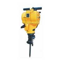
This document outlines the repair and maintenance procedures for the Atlas Copco PHE 3 and PHE 3X devices, focusing on detailed dismantling and assembly instructions for various components. The device appears to be a power tool, likely a hammer drill, given the references to a hammer mechanism, SDS-Plus reception, and components like a striker and planetary gear.
The Atlas Copco PHE 3 and PHE 3X are power tools designed for tasks requiring a hammer mechanism, such as drilling into hard materials. The device incorporates an SDS-Plus reception system, indicating its compatibility with SDS-Plus drill bits, which are commonly used for rotary hammer drills due to their quick-change capability and efficient power transfer. The internal structure includes a motor, a gear housing with planetary gears, a spindle, and a hammer mechanism with a striker and plunger, all working in conjunction to deliver both rotary and percussive action. The electrical components, including a switch, capacitor, and triac, control the motor's operation, while carbon brushes ensure electrical contact with the armature. The device is designed for robust performance, with various bearings and O-rings to ensure smooth operation and sealing against contaminants.
The device is operated via a switch lever, which likely controls different modes of operation (e.g., rotary drilling, hammer drilling). The SDS-Plus reception allows for quick and secure insertion and removal of drill bits, enhancing user efficiency. The handle is designed for user comfort and control, incorporating a silicone buffer for vibration dampening and a handle bolt for secure attachment. The motor cover and service cover provide access to internal components for maintenance while protecting them during operation. The overall design emphasizes durability and ease of service, as evidenced by the detailed repair instructions.
The manual provides comprehensive guidance for maintaining the PHE 3 and PHE 3X, ensuring longevity and optimal performance.
Regular maintenance is strongly recommended, especially if carbon brushes are cut off or the hammer mechanism fails. When performing maintenance, all parts of the maintenance set must be exchanged. Specific maintenance sets are provided for different voltage versions of the PHE 3 and PHE 3X.
The manual meticulously details the step-by-step process for dismantling and assembling various sections of the device.
At each maintenance, the tool must be lubricated as shown in the lubrication chart, which specifies the type and amount of grease for various components (e.g., spindle wheel toothing, back gear hollow, O-rings, needle bearing, plunger, cylinder inside/outside, striker, tumble drive boring, gear sleeve, ratchet/spindle wheel, angular wheel, thrust bearing). Used grease must be completely removed and replaced with new grease. The service set contains tubes with Darina and Tivela grease, and any remaining Darina grease should be used to evenly lubricate the gear box and spindle sleeve.
All parts, except electrical components, must be cleaned with cold cleaner. Care must be taken to prevent cleaner from entering encapsulated bearings. Electrical parts should be cleaned with a dry brush.
Dismantled parts should be visually checked for abrasion and exchanged if necessary.
Before assembly, all relevant parts must undergo an electrical test as described in the "Electrical and Mechanical Test Instruction" chapter. A final electrical examination is also required after assembly.
After assembly, a test run should be performed to check for strange noises.
All screwed connections in metal should be additionally secured with a screw locking device.
This comprehensive maintenance guide ensures that the Atlas Copco PHE 3 and PHE 3X devices can be effectively serviced, prolonging their operational life and maintaining their performance standards.
| Drill type | Pistol grip drill |
|---|---|
| Free speed | 2200 rpm |
| Air inlet size | 1/4 inch |
| Chuck size | 10 mm |
| Vibration level | 2.5 m/s² |
| Hole diameter range | 10 mm |