Do you have a question about the Atlas Copco PHE 16 RL-N and is the answer not in the manual?
Steps to remove the drill spindle and its components, including springs, rings, and balls.
Procedures for disassembling the gear box, involving removal of springs, discs, and levers.
Instructions for lifting the pillow block and spring, and removing the cylinder and percussion body.
Steps to remove the reduction gear shaft, wobble gear drive, coupling sleeve, and driver.
Guide to removing the bearing end plate, gasket, carbon brushes, and brush holder insulations.
Instructions for removing screws, armature, field, and power supply lead from the housing.
General advice on submitting the tool for regular maintenance and replacing parts.
Guidelines for cleaning tool parts with a cold cleaning agent and a dry brush for electrical parts.
Instructions to check disassembled parts for wear through visual inspection and replace worn parts.
Requirement to perform an electrical test on relevant parts before reassembly.
Steps for mounting the power supply lead, field, and electronic parts into the housing.
Instructions for fitting brush holder insulations, carbon brushes, and the bearing end plate.
Procedures for fitting the coupling sleeve and mounting the reduction gear wheel and complete gear.
Steps for mounting spring disc, bearings, spacer, disc, and percussion body into the cylinder.
Instructions for mounting disc springs, fastening the gear box, and fitting the mounting cone.
Steps for mounting the sleeve, sealing ring, balls, jumper ring, spacer, spring, and nosepiece.
Procedures for checking rotation direction, running in the machine, and performing final electrical tests.
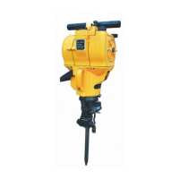
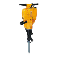
This document provides repair instructions for the Atlas Copco PHE 16 RL-N and PHE 20 N electric power tools. It details the disassembly, maintenance, and assembly procedures for various components of the device.
The Atlas Copco PHE 16 RL-N and PHE 20 N are electric power tools, likely hammer drills or rotary hammers, given the references to "hammer mechanism," "drill spindle," and "percussion body." These tools are designed for drilling and potentially hammering applications, indicated by the presence of a "hammer switch lever" and components related to a percussion mechanism. The "drill spindle" is the part that holds the drill bit, and the "wobble gear drive" and "reduction gear" suggest a robust transmission system for delivering power and torque. The "carbon brushes" and "armature" are typical components of an electric motor, indicating that these are electrically powered tools. The "gear box" houses the gears responsible for transmitting power and converting rotational motion.
While specific numerical technical specifications like power output, RPM, or impact rate are not explicitly stated in this repair manual, the document provides insights into the internal mechanics and precision required for the tool's operation. For instance, the "end play" of the wobble gear drive must be precisely 0.05 + 0.03 mm, highlighting the importance of tight tolerances for optimal performance and longevity. The "locating distance" for the sealing ring on the drill spindle is specified as 3.5 ± 0.2 mm, further emphasizing the need for accurate assembly. The document also mentions specific grease types and quantities for lubrication, such as "6 g Tivela" and "15 g Darina," which are critical for the smooth operation and wear prevention of moving parts. The drill bit size for removing the sealing ring is specified as 3 - 3.5 mm, indicating the scale of some internal components. The repair instructions are dated November 1995, suggesting the vintage of these particular models.
Based on the disassembly and assembly steps, the tool likely features a mechanism for easy drill bit changes, as indicated by the "nosepiece" and "sleeve" components on the drill spindle. The "hammer switch lever" suggests the ability to switch between different operating modes, such as drilling and hammer drilling, offering versatility for various tasks. The presence of a "housing" and "handle shells" indicates a design that encloses the internal components and provides a grip for the user. The "power supply lead" confirms it's a corded electric tool, requiring a connection to a power outlet. The "mounting cone" for the gear box and the various springs and discs suggest a robust and potentially adjustable mechanism for power delivery and impact. The "pillow block" and "cylinder" are integral to the percussion mechanism, implying effective impact delivery for demanding applications.
The manual is entirely dedicated to maintenance, emphasizing its importance for the tool's lifespan and performance. Key maintenance features include:
Overall, this manual provides a comprehensive guide for maintaining the Atlas Copco PHE 16 RL-N and PHE 20 N, ensuring their longevity and reliable operation through detailed repair and lubrication procedures.
| Brand | Atlas Copco |
|---|---|
| Model | PHE 16 RL-N |
| Category | Drill |
| Language | English |