Do you have a question about the Atlas Copco PHE 6 H and is the answer not in the manual?
Steps to dismantle the tool reception for the PHE 6 S model.
Steps to dismantle the tool reception for the PHE 6 H model.
Procedure for removing the carbon brushes from the machine.
Instructions for disassembling the handgrip assembly.
Steps to remove the armature from the motor housing.
Procedure for detaching the spindle sleeve for the PHE 6 S model.
Instructions for detaching the bearing housing for the PHE 6 H model.
Steps to dismantle the spindle sleeve for the PHE 6 S model.
Procedure to separate the driver from the barrel for the PHE 6 H.
Guide to lubrication points and types of grease used.
Instructions for performing a test run and listening for noises.
Requirement to perform an electrical test before reassembly.
This document provides repair instructions for the Atlas Copco PHE 6 H and PHE 6 S electric power tools. It details the disassembly, maintenance, and assembly procedures for various components of these devices.
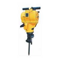
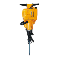
The Atlas Copco PHE 6 H and PHE 6 S appear to be rotary hammer drills, designed for heavy-duty drilling and chiseling applications. The presence of components like a spindle sleeve, anvil, piston, connecting rod, bevel gear, and a rotary stop indicates their capability for both rotary and impact functions. The "tool reception" sections suggest a system for quickly attaching and detaching various drill bits or chisels. The "carbon brushes" and "armature" sections point to an electric motor as the power source, typical for professional-grade power tools. The "crankshaft" and "reduction gear shaft" are integral to converting the motor's rotational energy into the necessary force for drilling and hammering.
While specific numerical specifications like motor power or impact energy are not explicitly listed in the provided pages, the detailed repair instructions imply a robust and complex mechanical design. The mention of specific Torx screwdriver sizes (TX 30), socket wrench sizes (SW 50), and torque values (e.g., 120.0 Nm for the nut PHE 6 S, 30.0 Nm for the driver PHE 6 H, 2.5 Nm for screws in plastic, 4.0 Nm for screws in metal, and 3 Nm for the clutch) highlight the precision required for assembly and maintenance, suggesting a high-performance tool. The lubrication plan specifies "Red grease (80 g) Mobil SHC 007" and "Blue grease (80 g) Mobil HP 22," indicating the types and quantities of lubricants essential for optimal operation and longevity. The instruction to use a 32 mm nut for the clutch (6) further specifies a tool requirement.
The design suggests features for user convenience and safety. The "auxiliary handle" (G/C) indicates a two-handed operation for better control and stability during use. The "dust guard cap" (3) on the PHE 6 H and "rubber cover" (2) on the PHE 6 S suggest protection against dust and debris, which is crucial in construction environments. The "switch lever" (C) and "retaining strap" (A) for tool reception imply a quick-change system for accessories. The "rotary stop" feature, detailed in the disassembly and mounting sections for PHE 6 S, suggests the ability to switch between rotary drilling and hammer-only modes, enhancing versatility. The "damping element" (2) in the handgrip implies vibration reduction for user comfort during prolonged operation.
The manual is primarily a maintenance guide, offering comprehensive instructions for servicing the tool.
| Brand | Atlas Copco |
|---|---|
| Model | PHE 6 H |
| Category | Drill |
| Language | English |