17
PAGE
Repair Instructions No.181.03/98
PHE 6 H / PHE 6 S
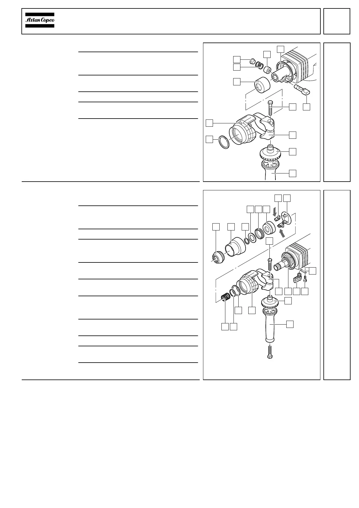
PHE 6 H:
Assembling the
tool reception
1 Insert the connecting ring (7).
2 Push the strap (A) over the neck of the
machine and tighten it with the bearing
bolt (9).
3 Mount the cone (2) and insert the restric-
tor (1).
4 Insert the latch (8) into the nosepiece.
5 Insert the distance sleeve (6) and the
spring (4).
6 Knock in the latch (5) with light hammer
blows until it is flush with the nosepiece.
PHE 6 S:
Assembling the
tool reception
1 Insert the switch lever (C) such that it
grasps the provided groove.
2 Slightly lift the switch lever (C), push the
retaining strap (A) under it and fasten it
with the two Allen screws (B).
3 Mount the connecting ring (D).
4 Push the strap (E) over the neck of the
machine and tighten it with the bearing
bolt (9).
5 Mount the cone (H) and insert the restric-
tor (J).
6 Mount the washer (K), the spring (L) and
the retention plate (8).
7 Depress the retention plate (8) against re-
silience and insert the latches (7) at the
sides.
8 Fit the retainer (6), the rubber stop (5) and
the stop (4).
9 Mount the spring ring (3).
10Fit the rubber cover (2) and push down the
end cover cap (1).
11Mount the auxiliary handle (G) completely
with the clamping ring (F).
Test Run
Electrical Test
Test run the machine and pay attention to noises.
Let the machine run-in.
Perform an electrical test on the machine (see chapter Electrical and Mechanical Test Instructions).
1
8
4
3
2
9
A
5
B
6
C
7
9
1
654
32
7 8
C B
A
D
F
G
HJ
KL
E
 Loading...