Safety Information Power Focus 3000
6
© Atlas Copco Industrial Technique AB - 9836 2156 01
the Spare part list, see under Remarks.
The entire product, or the WEEE parts, can be sent
to your “Customer Centre” for handling.
For more information, consult the website
http://www.atlascopco.com/.
Choose Products - Links and downloads, and
click EU RoHS and WEEE directives (ENG-
LISH only).
Installation
Installation checklist
This Power Focus is a control and monitoring
unit for electric assembly tools. The ready-to-
run fastening system consists of:
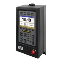
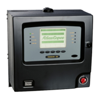
• a Power Focus controller. Two different hard-
ware versions are available, the Graph and the
Compact. The user interface and the dimen-
sions are the main differences between them.
• an RBU, Rapid Backup Unit, enabling the cor-
responding level of functionality (Bronze, Sil-
ver, Gold, X, DS)
• a tool cable, available in different models and
lengths
• and a tool. The Tensor S/ST/SL tool is avail-
able in different configurations and torque
ranges.
Installation procedure
1. Mount the controller on the wall or steel plate
with four M6 screw. If mounting on a wall,
make sure to use correct wall bracket (plug and
screw). If mounting on a steel plate, make sure
that the thickness of the plate is minimum 2
mm.
2. Open the locking mechanism
3. Open the controller slowly towards you, not to
cause injury or damage
4. Connect the tool cable, power cable etc.
5. Connect the RBU
6. Close the controller and lock it
7. Connect the power cable to a power supply
(115/230 V)
8. Turn the power on
Handling
Program a Pset - Compact
1. Press the AUTOSET key and ASEt/Ft appears
on the display
2. Choose final torque target by pressing +/- keys
3. Press the ENTER key to activate the Autoset
function
4. The Autoset symbol LED lights up
5. Make 5-8 tightening until the LED goes out
Optimum performance has been found and the sys-
tem is ready for production.
Program a Pset - Graph
1. Press the PROG key and select Pset then Quick
Prog with the arrow keys
2. Enter the final torque target with the alpha-nu-
merical keys
3. Press the ENTER key to activate the Autoset
function
4. The Autoset symbol LED lights up (the LED is
placed at the very bottom on the right side of
the front panel)
5. Make 5-8 tightening until the LED goes out
6. Press the RESULT key
Optimum performance has been found and the sys-
tem is ready for production.
Preventing ESD problems
The components inside the tool and controller are
sensitive to electrostatic discharge. To avoid future
malfunction, make sure that service and mainte-
nance is carried out in an ESD approved work en-
vironment. The figure below shows an example of
an appropriate service work station.
Useful information
 Loading...