CIRCUIT DIAGRAM
2954 2100 01 57
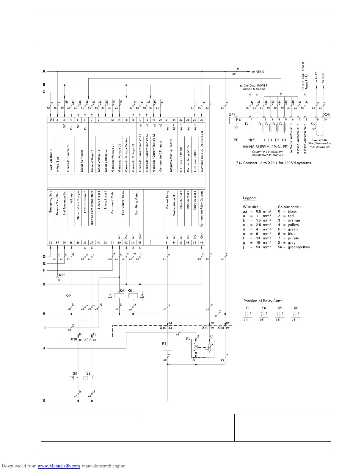
K4 W/L-Invertor Relay S2a Emergency Stop V2 Diode
K5 Starter Relay S2b (see Power Circuit) X10 Connector Wire Harness
K6 Fuel Solenoid Relay S8 High Coolant Temp. Switch X25 Customer’s Terminal Strip
M1 Starter Motor S9 Low Oil Pressure Switch Y1 Fuel Stop Solenoid
R2 Excitat. Resistor 47 ohm S20 ON/OFF-switch
A
B
C
D
E
F
G
H
I
J
K
!
""
#
$
%
&
#
#
#
#
'()&'*( !+,
- -.-
)
#//%
'()&'*( !+,
) 0 )
)
!'' 1 23 )
4*5
+'( '6 7
8 98 )8:
8 98 8 :
8 98 )8:
8 98 )8:
58 98 8 :
8 98 8 :
18 98 8 :
*8 98 8 :
;8 98 8 :
2( 5 7
8 98 2<
8 98 (5
8 98 (*
8 98 322=
8 98 *(
8 98 2
8 98 (2
8 98 *(3
898 *(>322=
!,
"?
!, @AB
@AB9 4 ) 1( C5.3
D" "E!!4F @!$$!,B
!" #
#$
% #$
% #
4 4 4 4
-? -? -?-? -?
1( 23
!( 23
(2 2( G(
23
23
23
4= '2 !((
G'* 2/((
+>4
5 !(( "
"(>"
,(*3 "
"' #(3 (*(
"( 23
-2 (2 23
@C5B
#'(3
#'(3
> C5 @#$B
C5 @#%B
H(( (
D' (
D' C2* 4
D' C2* 4
D' C2* 4
H(( C2* 4
H(( C2* 4
H(( C2* (2
H(( C2* 4
H(( ((/(1 4
H(( ((/(1 4
H(( ((/(1 4
1( /%'
D*' !'<. @/B
'2 !(( @C&B
2/ @C&B
-2 4I2 @C&B
1( C&.' @ C5B
 Loading...


