- 25 -
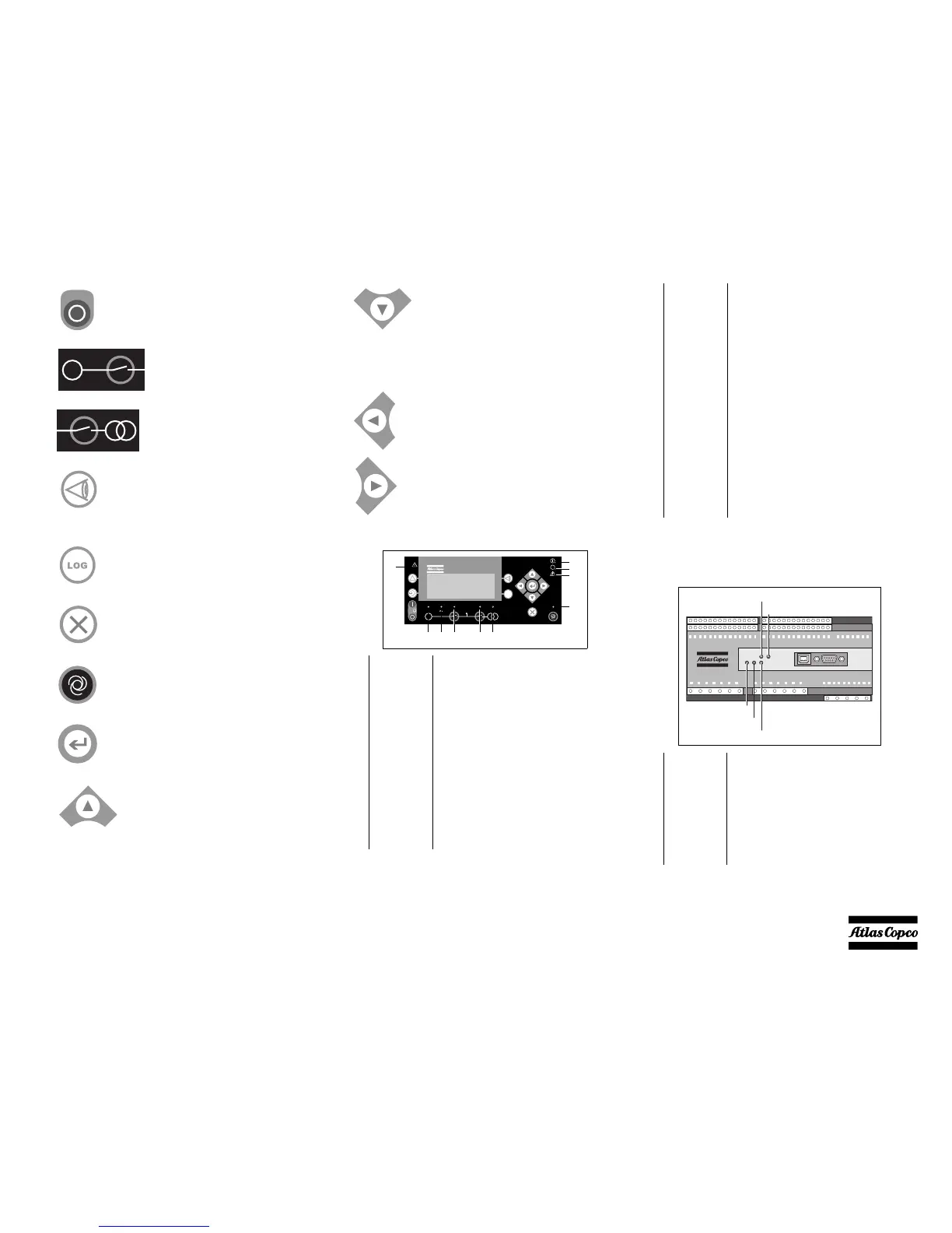
Following LEDs are used on the Qc4002™
The main Qc4002™ control unit includes 5
LEDs
STOP: Stop of the gen-set if SEMI-
AUTO or MANUAL is selected.
GB: Manual activation of
close breaker and open
breaker sequence if SEMI-
AUTO is selected.
MB: Manual activation of
close breaker and open
breaker sequence if SEMI-
AUTO is selected.
VIEW: Shifts the first line displaying
in the setup menus.
LOG: Displays the LOG SETUP
window where you can choose
between the Event, Alarm and Battery
logs. The logs are not deleted when the
auxiliary supply is switched off.
BACK: Jumps one step backwards in
the menu (to previous display or to the
entry window).
MODE: Changes the menu line (line
4) in the display to mode selection.
SEL: Is used to select the underscored
entry in the fourth line of the display.
UP: Increases the value of the selected
set point (in the setup menu). In the
daily use display, this button function
is used for scrolling the View lines in
V1 or the second line (in the setup
menu) displaying of generator values.
DOWN: Decreases the value of the
selected set point (in the setup menu).
In the daily use display, this button
function is used for scrolling the View
lines in V1 or the second line (in the
setup menu) displaying of generator
values.
LEFT: Moves the cursor left for
manoeuvring in the menus.
RIGHT: Moves the cursor right for
manoeuvring in the menus.
1Alarm LED flashing indicates that
unacknowledged alarms are present.
LED fixed light indicates that ALL alarms
are acknowledged.
2Power LED indicates that the auxiliary supply is
switched on.
3 Self check
OK
LED indicates that the self check is OK.
4Alarm
inhibit
Please refer to Alarm inhibit in the chapter
‘Additional functions’.
5Run LED indicates that the generator is
running.
6 Generator
voltage
LED green light indicates that the voltage/
frequency is present and OK.
Qc4002
G
!
OK
LOG
5
1
67 8
2
3
4
10
9
7 (GB) ON LED green light indicates that the
generator breaker is closed.
LED yellow light indicates that the
generator breaker has received a command
to close on a black BUS, but the breaker is
not yet closed due to interlocking of the
GB.
LED is flashing orange if the ‘Spring load
time’ signal from the breaker is missing.
8(MB) ON LED indicates that the mains breaker is
closed.
9 Mains
voltage
LED is green, if the mains is present and
OK.
LED is red at a measured mains failure.
LED is flashing green when the mains
returns during the ‘mains OK delay’ time.
10 Auto LED indicates that auto mode is selected.
1Power Green LED indicates that the voltage
supply is switched on.
2 Self check
OK
Green LED indicates that the unit is OK.
3Alarm
inhibit
Green LED indicates that the inhibit input
is ON.
4 CAN 2
5 CAN 1
3
2
1
5
4
 Loading...