- 24 -
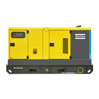
Control and indicator panel Qc4002™
General description Qc4002™ control panel
A2..... Qc4002™ display
F10 ... Fuse
The fuse (10 A) activates when the current from the
battery to the engine control circuit exceeds its
setting. The fuse can be reset by pushing the
button.
S2..... Emergency stop button
Push the button to stop the generator in case of an
emergency. When the button is pressed, it must be
unlocked, before the generator can be restarted.
The emergency stop button can be secured in the
locked position with the key, to avoid unauthorized
use.
S11... Frequency selector switch (50 Hz/60 Hz)
Allows to choose the frequency of the output
voltage: 50 Hz or 60 Hz.
S20... ON/OFF switch
Position O: No voltage is applied to the Qc4002™
module, the generator will not start.
Position I: Voltage is applied to the Qc4002™
module, it is possible to start up the generator.
X25... Connection block
Inside the cubicle. Allows customer connections.
X30... Connector X30
Connector for communication with other
generators with Qc4002™ when paralleling.
X31... Connector X31
Connector for communication with other
generators with Qc4002™ when paralleling.
X32... Connector X32
Connector for PMS communication with other
generators with Qc4002™ when paralleling.
Qc4002™ module
The Qc4002™ module is located inside the control panel,
and communicates with a display unit, located in front of
the control panel. This control module will carry out all
necessary tasks to control and protect a generator,
regardless of the use of the generator.
This means that the Qc4002™ module can be used for
several applications.
Pushbutton and LED functions
Following pushbuttons are used on the
Qc4002™
Changing the output frequency is only
allowed after shutdown.
Refer to circuit diagram for
the correct connection.
INFO: Shifts the display 3 lower lines
to show the alarm list.
JUMP: Enters a specific menu
number selection. All settings have a
specific number attached to them. The
JUMP button enables the user to select
and display any setting without having
to navigate through the menus.
START: Start of the gen-set if SEMI-
AUTO or MANUAL is selected.
w
w
w
.
a
t
l
a
s
c
o
p
c
o
.c
o
m
Q
c
4002
G
!
O
K
L
O
G
 Loading...