- 51 -
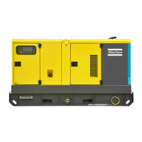
Options available for QAS 250-330 John Deere units
Circuit diagrams
The engine control circuit diagrams and the power circuit
diagrams for the standard QAS 250-330 John Deere units,
for the units with options and for the units with combined
options are:
Power circuit
Unit Circuit
QAS 250-330 1310 3200 11
QAS 250-330 Qc4002™ 1310 3200 24
Controller circuit
Unit Circuit
QAS 250-330 Qc1002™ 1310 3200 12
QAS 250-330 Qc4002™ 1310 3200 25
Overview of the electrical options
The following electrical options are available:
– Automatic battery charger
– Engine coolant heater
– Outlet sockets (S)
– Triple voltage (3V)
Description of the electrical options
Automatic battery charger
The automatic battery charger charges the battery when
external power is provided via the X7 connection. When
the battery is fully charged the charger automatically
changes to maintenance mode and provides a trickle
charge to maintain the battery level. The charger has
LED's on the front panel to identify when power is applied
to the charger and when the batteries are being charged.
To use the batery charger:
– Provide external power (120V) to the X7 connector,
located on the side of the power cubicle.
Engine coolant heater
To make sure that the engine can start and accept load
immediately, an external cooling water heater (1500 W,
120 V) is provided which keeps the engine temperature
between 38°C and 49°C.
Outlet sockets (S)
A brief description of all outlet sockets and circuit
breakers provided on the generator is given hereafter:
Q1.1 and Q1.2 Circuit breaker for X1
Interrupts the power supply X1 when a short-
circuit occurs at the load side, or when the
overcurrent protection is activated. When
activated, Q1.1 and Q1.2 interrupts the three
phases towards X1. It must be reset manuallly after
eliminating the problem.
Q2.....Circuit breaker for X2
Interrupts the power supply to X2 when a short-
circuit occurs at the load side, or when the
overcurrent protection (16 A) is activated. When
activated, Q2 interrupts one phase (L3) towards
X2. It can be activated again after eliminating the
problem.
Q3.....Circuit breaker for X3
Interrupts the power supply to X3 when a short-
circuit occurs at the load side, or when the
overcurrent protection (125 A) is activated. When
 Loading...