Common (12 Vdc)
Engine CAN-bus Interface
GND
CAN-L
CAN-H
Magnetic Pick-up (Tacho)
Input
Input Fuel Level (VDO)
Coolant Temp (VDO)
W/L-Input D+
Oil Pressure (VDO)Input
GND
Input
Common for VDO-inputs (0 Vdc)
12/24 Vdc (Batt+)
Generator Voltage L2
Generator Voltage L1
NO
Com
Fuel Control Relay
Com
NO
Remote Start
Common for Relay Outputs
Central Alarm Horn
Low Oil Pressure
High Coolant Temperature
Preheat Relay
Generator Contactor
876159 121314 1617
252726 32 33 34
0 Vdc (Batt-)
24 36
1234
3521 2319
18
A1
5
Input
Input
Input
Input
Input
Input
Spare <Low Coolant Level>
Start Relay Output
Start/Stop
Qc1002
NO
NO
Com
NO
AB C DEFG HI JKL
PE
1
X25
23
X25
4PE
X25
to A1.18
18
a3
38
a0
12
a6
to Generator Contactor A1 <--
to Generator Contactor A2 <--
Sx
Sx=Remote
Start/Stop-switch
to A1.17
19
a3
Generator Contactor
Output: 12Vdc, max.8Adc1
17
a2
12
a6
125
a0
126
a0
17
a2
12
a6
A
P1
U1
x0
1U1
x0
126
a0
125
a0
125
a0
126
a0
to Circ.Diagr
POWER
Fuses F1-F2
14
c3
5
c3
15
a3
5
c3
14
c3
14
a3
38
a0
15
a3
12
a6
V
P4
125
a0
126
a0
to Circ.Diagr
POWER
Colour code :
0 = black
1 = brown
2 = red
3 = orange
4 = yellow
5 = green
6 = blue
7 = purple
8 = grey
9 = white
54 = green/yell.
Legend
Wire size :
a = 1 mm²
b = 1.5 mm²
c = 2.5 mm²
d = 4 mm²
e = 6 mm²
f = 10 mm²
g = 16 mm²
h = 25 mm²
i = 35 mm²
j = 50 mm²
k = 70 mm²
l = 95 mm²
lx = 95 mm² EPR-CSP (BS6195-4C)
bx = 1.5 mm² NSGAFOeU
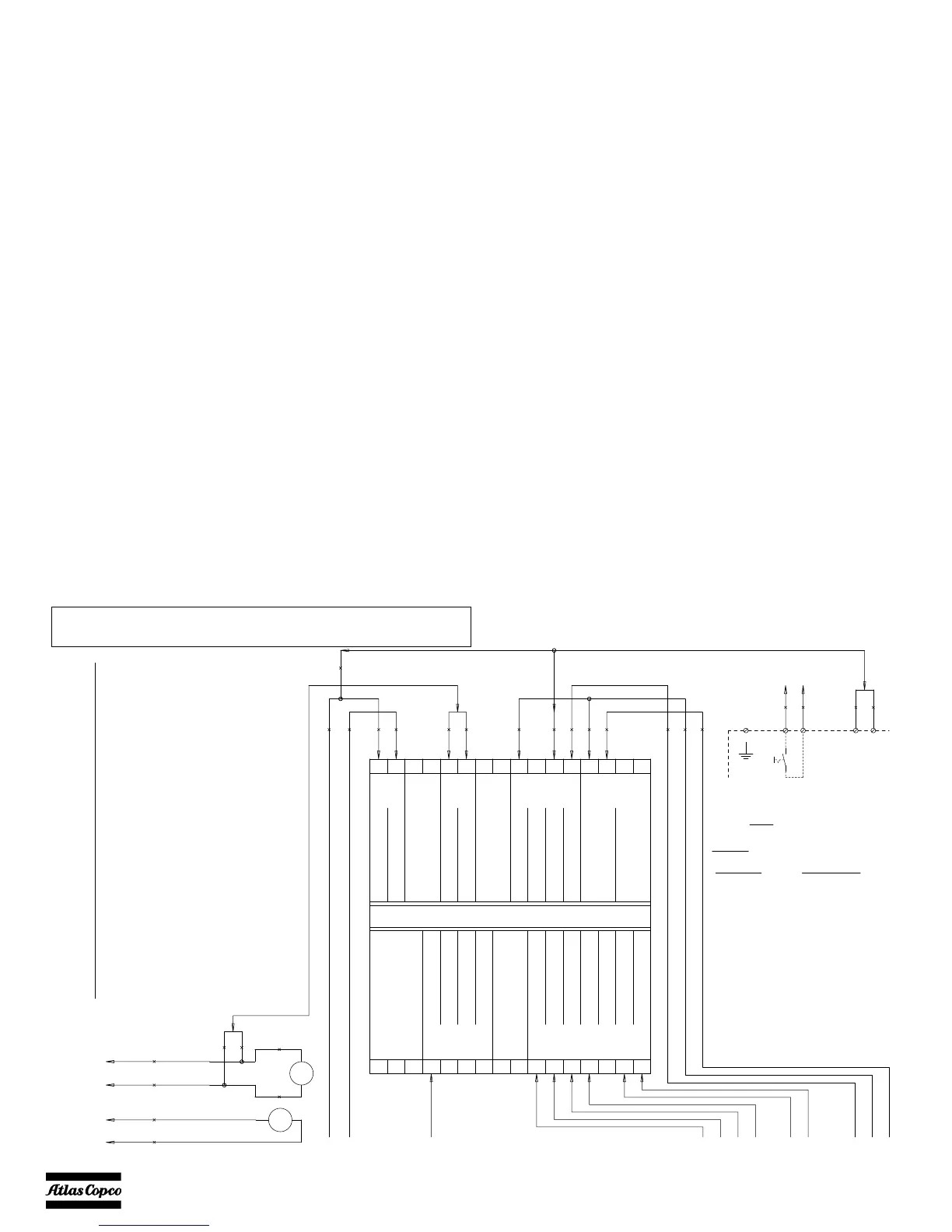
9822 0997 83/04
Applicable for QAX 12-20-24-30-35 - Qc1002™
A1 Generator control unit
(set A1 in unit-type 4)
F10 Fuse 10 A
G1 Battery 12 Vdc
G2 Charging alternator
K0 Starter solenoid
K4 W/L-invertor relay
K5 Starter relay
M1 Starter motor
P1 Amperemeter
P4 Voltmeter
R2 Excitation resistor 47 Ohm
S2a Emergency stop
(S2b: see Power Circuit)
S8 High coolant temperature switch
S9 Low oil pressure switch
S20 On/Off/Remote switch
V2 Excitation diode
X10 Connector wire harness
X25 Customer's terminal strip
Y1 Fuel stop solenoid
 Loading...