- 61 -
9 Options available for
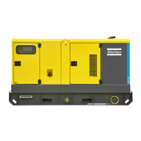
QAX 12-20-24-30-35
units
9.1 Circuit diagrams
The engine control circuit diagrams and the power
circuit diagrams for the standard QAX units, for the
units with options and for the units with combined
options are:
Power circuit
Unit Circuit
QAX 12 - 1-phase 9822 0997 36
QAX 12-20-30 - 3-phase 9822 0997 35
QAX 24-35 - 3-phase 9822 0997 32
Engine control circuit
Unit Circuit
QAX 12-20-24-30-35 - Qc1002™ 9822 0997 83
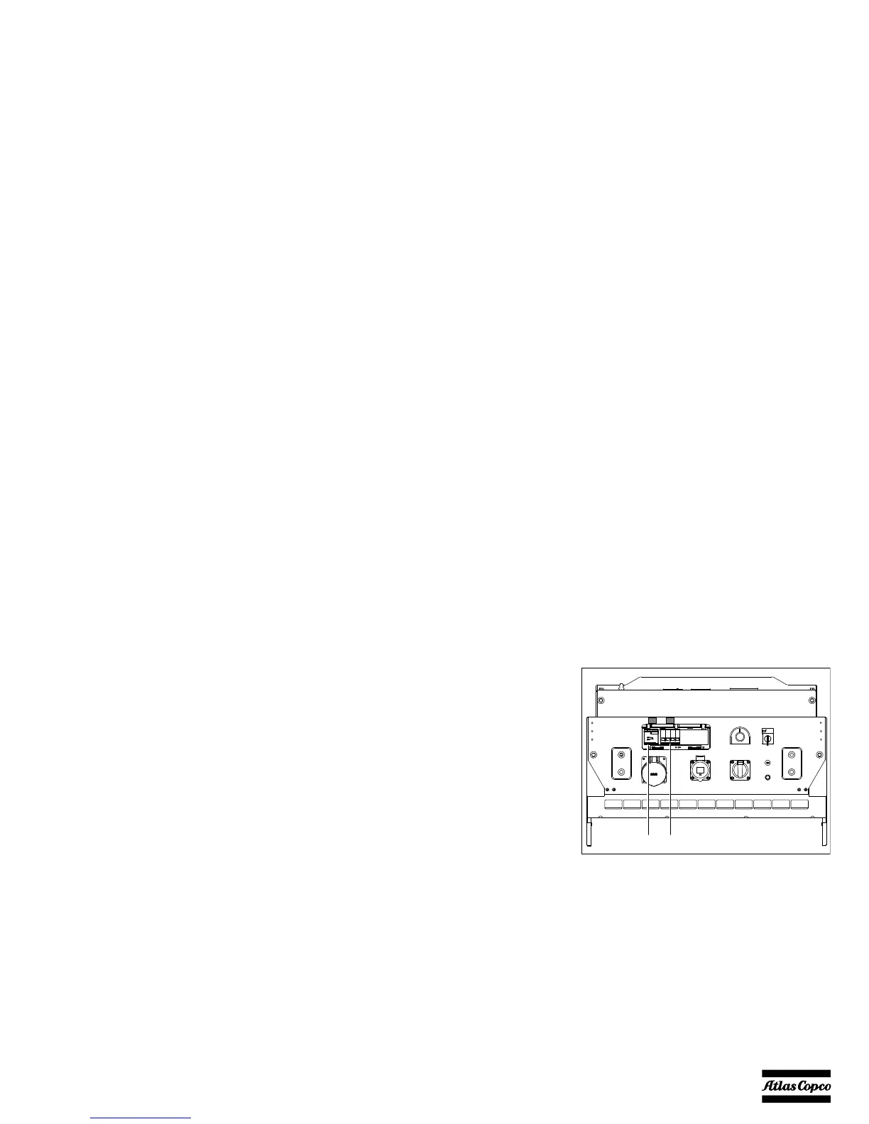
9.2 Overview of the electrical
options
The following electrical options are available:
– Earth leakage relay
– IT-relay (only for QAX 12-20-30)
– Single phase socket (only for QAX 12)
– 16 A or 32 A middle socket (only for QAX 30)
–COSMOS™
9.3 Description of the electrical
options
9.3.1 Earth leakage relay
The Earth relay option provides a detector that will
trip the main circuit breaker Q1 when an earth fault
current is detected.
N13 .....Earth leak detector
Detects and indicates an earth fault current
and activates the main circuit breaker Q1.
The detection level can be set at 30 mA fixed
with instantaneous trip but can also be
adjusted between 0.1 A and 1 A with time
delayed (0 - 0.5 sec) trip. N13 has to be reset
manually after eliminating the problem
(reset button marked R).
Q1 .......Main circuit breaker
 Loading...