- 18 -
2.3 Mechanical features
The mechanical features described in this chapter are
standard provided on this generator. For all other
mechanical features, see chapter “Overview of the
mechanical options” on page 67.
2.3.1 Engine and alternator
The alternator is driven by a fluid-cooled diesel
engine. The engine’s power is transmitted through a
direct disc coupling.
The generator houses a single bearing alternator with
a dedicated voltage regulator.
The synchronous brushless alternator has Class H
rotor and stator windings in an IP23 housing.
2.3.2 Cooling system
The engine is provided with a water cooler. The
cooling air is generated by a fan, driven by the engine.
2.3.3 Safety devices
The engine is equipped with low oil pressure and high
coolant temperature shut-down switches.
2.3.4 Bodywork
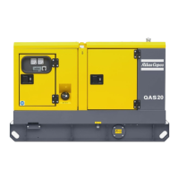
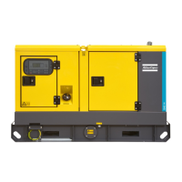
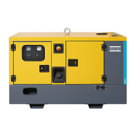
The alternator, the engine, the cooling system, etc. are
enclosed in a sound-insulated bodywork that can be
opened by means of side doors (and service plates).
The generator can be lifted by using the lifting eye
integrated in the bodywork (roof). To be able to lift
the QES 9-14-20-30-40 / QES 11-16-25-35-50 by
means of a forklift, rectangular slots are provided in
the frame.
The earthing rod, connected to the generator’s earth
terminal is located at the bottom of the frame on the
outside.
2.3.5 Control panel
The control panel grouping volt and amp meters,
control switch etc., is placed at the rear end.
2.3.6 Data plate and serial number
The generator is furnished with a data plate showing
the product code, the unit number and the power
output (see chapter “Data plate” on page 114).
The serial number is located on the right-hand front
side of the frame.
2.3.7 Drain plugs and filler caps
The drain holes for the engine oil, the coolant and the
plug for the fuel, are located and labelled on the
frame. The fuel drain plug is located at the front, the
others at the service side.
The drain flexible for engine oil can be brought to the
outside of the generator through the drain hole.
The filler cap for the engine coolant is accessible via
an opening in the roof. The fuel filler cap is located in
the side panel.
2.3.8 Spillage free skid
A Spillage free skid with forklift slots allows the
customer to transport the generator easily with a
forklift. It avoids accidental spilling of engine fluids
and thus helps to protect the environment.
The leaking fluid can be removed via drain holes,
secured by drain plugs. Tighten the plugs firmly and
check for leakages. When removing the leaking fluid,
observe all relevant local legislation.
The drain hole can also be used to
guide external fuel tank
connections. When connecting an
external fuel tank, use the 3-way
valves. Refer to chapter “External
fuel tank connection (with/without
quick couplings)”.
 Loading...


