- 59 -
FUNCTIONAL DESCRIPTION OF GENERATOR (OPTION)
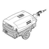
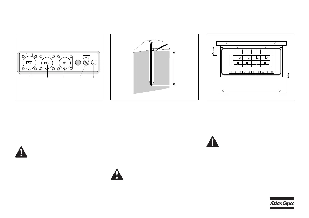
Control panel (generator) Earth pin
Start the unit in accordance with the normal
procedure (see section Starting / Stopping). Let the
motor warm up until it reaches operational
temperature. Turn the green switch S7 to position 1.
The normal control system is switched off and the
motor speed increases to reach the maximum.
The green lamp H3 in the switch S7 is activated,
showing that sockets X1, X2 and X3 are under
tension.
The generator can be switched off by turning the
green switch S7 to position 0.
Generator control box
Protective device
The generator is protected by circuit breakers that
switch off if a connected electrical device has an
electrical fault.
H3 Lamp (green, power ON)
S7 Switch (generator - compressor)
X1 Socket 110 V/ 32 A
X2 Socket 110 V/ 16 A
X3 Socket 110 V/ 16 A
GND Terminal earth cable
Before switching on the generator,
always place the earth pin in position.
Check the cable connection between
earth pin and the GND-terminal on the
unit.
110V WITHOUT AUTOMATIC CONTROL SYSTEM
(X3) (H3/S7) (GND)(X2)(X1)
Avoid high inductive loads (e.g.
welding). High inductive loads can
damage the generator.
Q1 Main circuit breaker 2-pole
Q2 Circuit breaker 2-pole
Q3 Circuit breaker 2-pole
Q4 Circuit breaker 2-pole
Before connecting an electrical device,
always check the data listed on the rating
plate.
 Loading...