1100..44 EElleeccttrriiccaal sl syysstteem / m / GGeenneerraal / l / SSaaffeetty cy chheecckk
Safety checkSafety check
Important!Important!
The function of the external The function of the external components in the steering servo system should becomponents in the steering servo system should be
checked after every service and after all work carried out in checked after every service and after all work carried out in the electrical system.the electrical system.
All function tests of the safety system should be carried out with the truck speedAll function tests of the safety system should be carried out with the truck speed
controller in neutral.controller in neutral.
The steering servo systemThe steering servo system
The steering servo system has a number of safety monitors, partly to check the regulatorThe steering servo system has a number of safety monitors, partly to check the regulator
circuits but also to ccircuits but also to check external circuits and components such as the steering wheelheck external circuits and components such as the steering wheel
sensorsensor, steering motor , steering motor and end position sand end position sensors.ensors.
A function test of the A function test of the steering servo system safety functions should result in it steering servo system safety functions should result in it not beingnot being
possible to activate the control system and drive system, and also that it should not bepossible to activate the control system and drive system, and also that it should not be
possible to put the possible to put the brake in unbraked position.brake in unbraked position.
The monitoring system for the The monitoring system for the steering wheel sensor and its cabling are steering wheel sensor and its cabling are checked bychecked by
separating the connector to the steering separating the connector to the steering wheel sensorwheel sensor, which should result in , which should result in an erroran error
code, seecode, see "Error codes, steering servo regulator, EPS" on page 10.61"Error codes, steering servo regulator, EPS" on page 10.61..
The steering motor monitor system is checked by disconnecting a cable connection to theThe steering motor monitor system is checked by disconnecting a cable connection to the
motor, either on the motor or on the regulator. An error code should then be shown whenmotor, either on the motor or on the regulator. An error code should then be shown when
turning the steering wheel, seeturning the steering wheel, see "Error codes, steering servo reg"Error codes, steering servo regulator, EPS" on page 10.61ulator, EPS" on page 10.61..
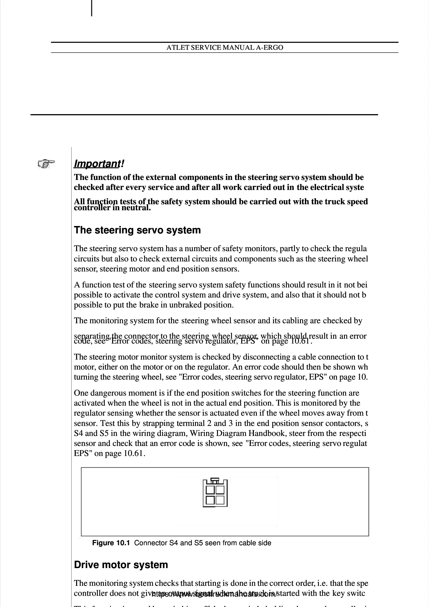
One dangerous moment is if the end position switches for the steering function areOne dangerous moment is if the end position switches for the steering function are
activated when the wheel is not in the actual end position. This is monitored by theactivated when the wheel is not in the actual end position. This is monitored by the
regulator sensing whether the sensor is actuated even if the wheel moves away from theregulator sensing whether the sensor is actuated even if the wheel moves away from the
sensor. Test this by strapping terminal 2 and 3 in the end position sensor contactors, seesensor. Test this by strapping terminal 2 and 3 in the end position sensor contactors, see
S4 and S5 in S4 and S5 in the wiring diagram, Wiring Diagram Handbook, steer from the the wiring diagram, Wiring Diagram Handbook, steer from the respectiverespective
sensor and check that an error code is shown, seesensor and check that an error code is shown, see "Error codes, steering "Error codes, steering servo regulator,servo regulator,
EPS" on page 10.61EPS" on page 10.61..
Drive motor systemDrive motor system
The monitoring system checks that starting is The monitoring system checks that starting is done in the correct done in the correct orderorder, i.e. , i.e. that the speedthat the speed
controller does not give an output signal when the truck is started with the controller does not give an output signal when the truck is started with the key switch.key switch.
Thi f i i d b i hi ff h k i h h ldi h d ll iThi f i i d b i hi ff h k i h h ldi h d ll i
Figure 10.1Figure 10.1 Connector S4 and S5 seen from cable sideConnector S4 and S5 seen from cable side
10_013_SM_A-ERGO_S4 S5 S8.eps
10_013_SM_A-ERGO_S4 S5 S8.eps
33
11
22
44
 Loading...