3
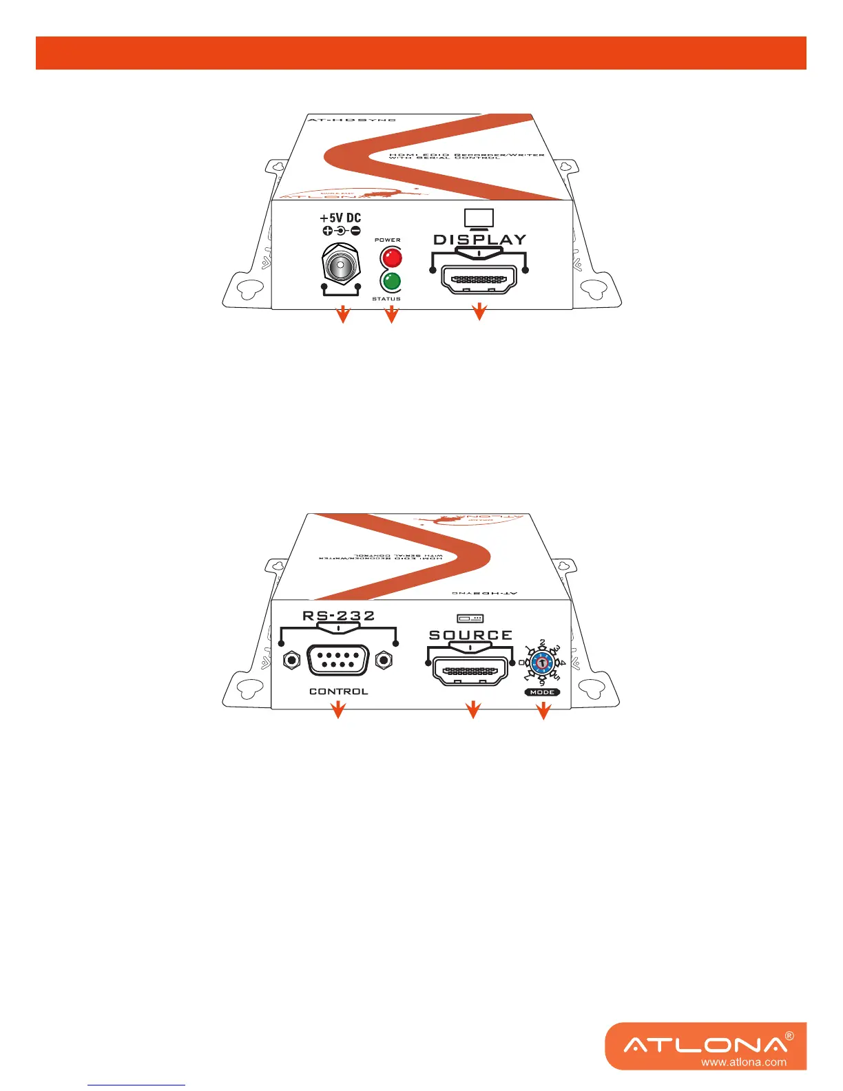
PANEL DESCRIPTION
Display Side
1. Connect to a 5V DC power supply unit.
2. Red light indicates the power on/off status. Green light indicates if the AT-HDSync is in the
process of reading or writing EDID or sync detection.
3. Connect to a HDMI
™
display.
Source and Control Side
4. Connect to a PC for RS-232 serial control to read/write EDIDs from/ to the display
5. Connect to a HDMI
™
source device so the AT-HDSync will be the bridge between the HDMI
™
source and display
6. Mode 0 = [Video] – supports up to HDMI 1.3 output. [Audio] – supports up to 7.1ch output
Mode 1 = [Video] – supports up to HDMI 1.3 output. [Audio] – lock to stereo audio output
Mode 2 = [Video] – locks to HDMI 1.2 output. [Audio] – supports up to 7.1ch output
Mode 3 = [Video] – locks to HDMI 1.2 output. [Audio] – lock to stereo audio output
Mode 4 = [Video] – DVI display mode. [Audio] – no audio output
Mode 5 = [Safe Mode] – uses default EDID with video supported up to 1080p
Mode 6 = [Recording Mode] – Learning EDID from HDMI output manually
Mode 7 = [Serial Control Mode] – Control the AT-HDSync by software via RS-232
1
2
3
4
5
6