Microcontroller
5-115
Using the Atmel AT89C1051 or
AT89C2051
XTAL1
The tester will apply logic level signals to this pin during
flash memory write and erase operations. There are two
things to remember about this pin.
1. The pin must be accessible to the tester, i.e. it must
be contactable by probe in a vacuum fixture.
2. Because the tester will force high and low signals
on this pin, you must design other circuitry on this
pin to permit and tolerate the logic level signals
applied by the tester.
P3 Pins P3.2 .. P3.5 and P3.7
The tester applies logic level signals to these five pins dur-
ing flash memory write and erase operations. There are
three things to remember about this group of pins.
1. The pins must be accessible to the tester, i.e. they
must be contactable by probes in a bed-of-nails fix-
ture.
2. If your application uses these pins as inputs, and
any other chips have their outputs connected to
these pins, the other chips’ outputs must be capable
of being disabled by the tester, or in any case must
tolerate the logic level high and low signals applied
by the tester. Alternatively you may design a 500 Ω
resistor in series with the other chip’s outputs. The
resistor will protect the other chip from excessive
backdrive, and will also prevent the other chip from
interfering with the tester’s signals during the flash
memory writing or erasing processes. Pay special
attention to intermittent signal sources such as
interrupts or external or external timing inputs that
are usually connected to P3.2, P3.3, P3.4.
3. Flash memory writing and erasing cycles generate
activity in other parts of the circuit. If any other chips
or subsystems on the board are designed to
respond to the P3 signals, they will receive unusual
instructions during the writing and erasing cycles.
Be sure that this unusual activity does not damage
them. Things to look for are other in-circuit writable
nonvolatile devices, high current drivers, fusible
squibs, etc. If any such exist, the 500 Ω resistor
method described for RST will also allow the tester
to prevent the sensitive subsystems from seeing the
unusual signal activity. Because the flash writing
signals are logic level, not 12-volt, the zener diodes
noted for RST are not necessary on the P3 signals.
See Figure 4.
Note on V
PP
Generation of V
PP
by the DFP on channel 223 presents no
danger to the conventional digital driver and receiver on
channel 223, because the conventional driver and receiver
are disconnected by a D relay during DFP operations. In
your DFP program, make sure to set V
PP
to zero and dis-
connect the V
PP
relay before exiting from ptprog.c.
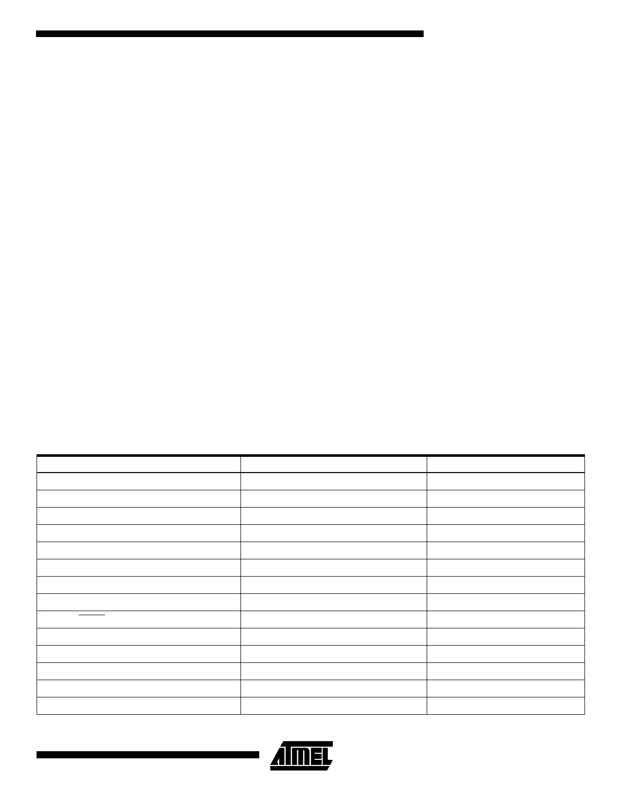
AT89C1051/205252 Pin Name DR2p Signal Name/Node# Notes
P1.0 192 (DR2p 0 - group A) Portwise Bidirectional
P1.1 193 (DR2p 0 - group A)
P1.2 194 (DR2p 0 - group A)
P1.3 195 (DR2p 0 - group A)
P1.4 196 (DR2p 0 - group A)
P1.5 197 (DR2p 0 - group A)
P1.6 198 (DR2p 0 - group A)
P1.7 199 (DR2p 0 - group A)
P3.2/PROG
200 (DR2p 0 - group B) Outputs from DFP to DUT
P3.3 201 (DR2p 0 - group B)
P3.4 202 (DR2p 0 - group B)
P3.5 203 (DR2p 0 - group B)
P3.7 204 (DR2p 0 - group B)
RST/V
PP
223 (DR2p 0 - group D) V
PP
supplied by DFP

 Loading...


