59
4929B–AUTO–01/07
ATA6264 [Preliminary]
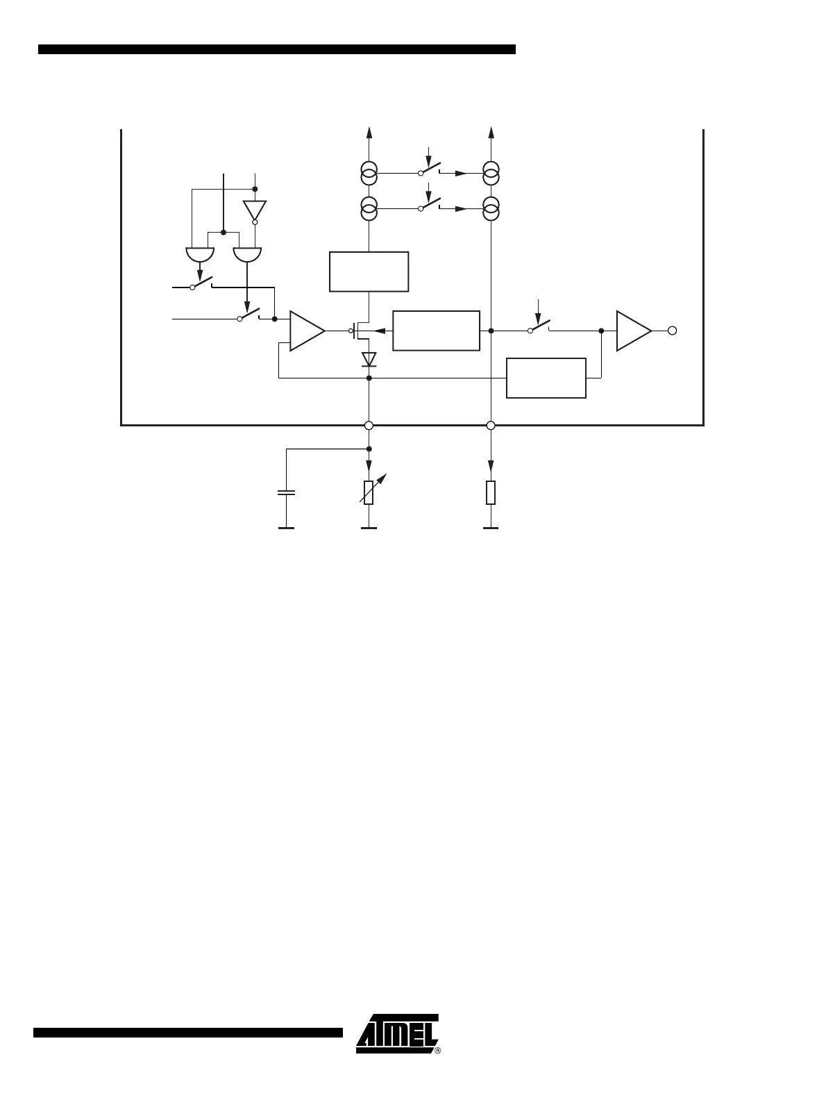
Figure 18-1. Functional Principle of the IASG Interface
Necessary for operation:
V
VCORE
and V
VPERI
> Reset threshold, V
EVZ
= 9V to 40V for operation with IASGx switched to 5V
V
VCORE
and V
VPERI
> Reset threshold, V
EVZ
= 15V to 40V for operation with IASGx switched to 10V
V
INT
= 3.7V to 5.47V, V
CP
> V
EVZ
+ 7V
Operating conditions of all other supply pins:
V
K30
and V
VSAT
are within functional range limits, T
j
= –40°C to 150°C
Other pins:
As defined in Section 4. ”Functional Range” on page 8, C
IASGx
≥ 10 nF and
825Ω≥R
ISENS
≥ 5kΩ
Serial
interface
Serial
interface
UZP
Current mirror
Serial
interface
Analog
multiplexer
Short circuit
protection
10
15
IASGx
C > 10 pF
RIASGx
I = f(R)
I/10
or
I/15
ISENS
Resistive
sensor
Current limit
if V
ISENS
>V
PERI
V
V1
V
V2
1
1
-
+
R
ISENS
 Loading...