PAGE 7
DOMESTIC EDGER PARTS LIST
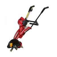
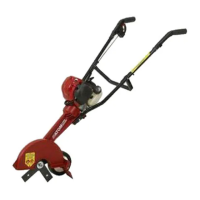
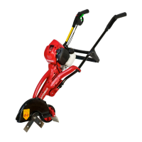
DOMESTIC MODEL 430 – 2 STROKE
63898MI-010711A
PROBLEM CAUSE ACTION
1. Blades do not turn Loose blade nut or incorrect assembly. Tighten blade nut (or add washer under nut).
when operating
Blade cover filled with dirt/grass/mud. Clean.
Blade stops under load when blade depth Cut less depth.
is too low.
Clutch slipping. Cut less depth, clean or run engine at full throttle.
2. Motor lacks power or Cutting too deep. Raise cutting depth and see (1) above.
blade stops rotating Carburettor requires adjustment.
3. Heavy vibration Wrong blade fitted. Only use ORIGINAL Atom blade set #43105
Worn clutch or clutch drum or damaged Take to service dealer.
drive.
4. Engine will not run or Ignition switch is OFF. Turn switch on.
runs and stops
Choke ON. Push choke to OFF position.
Partially empty fuel tank/dirty fuel tank. Fill tank/clean.
Primer bulb not pushed enough times. Press primer bulb fully and slowly 10 times.
Engine is flooded Use starting procedure without choke.
KEY# PART NO. DESCRIPTION
1 40650 SCREW M5 X 36
3 40651 SCREW M6 X 16
4 40652 NUT NYLOC 5MM
5 42111 WHEEL SEAL 27.2 X 12.6
6 43105 BLADE 10.7” X 48 X 1.9 (SET OF 2)
7 43112 BLADE DRUM
8 43114 BLADE SHAFT DRIVE
9 43128 WARNING LABEL BLADE COVER
10 43172 NUT NYLOC 3/8” UNC
11 43198 TRIGGER COMP. SPRING
12 43199 SPRING SMALL
13 43218 3/8” FLAT WASHER
14 43227 GREASE
15 43245 CROWN GEAR WITH BUSH
16 43452 HT. ADJ. COMP SPRING
17 43719 DEBRIS DEFLECTOR SPRING
18 43790 SCREW 5.5MM FOR PLASTIC
19 43860 BEARING 32 X 10 X 12 +4MM
20 44006 NUT 1/4” UNC
21 44060 UNIVERSAL HANDLE TUBE
22 44302 HEIGHT ADJ ARM PIN
23 44304 WHEEL AXLE BOLT 3/8” X 5.5”
25 44318 CLUTCH DRUM CUP 54MM
26 63424 ENGINE ATOM 26CC SCF
28 62843 HEX BOLT 3.5 X 1/4 BSW
29 62912 FLANGE HUB
30 62917 EDGER GEAR SEAL
31 62919 NUT NYLOC 1/4” UNC
32 62925 SHAFT UNIVERSAL
33G 63897GP LH+RH GREEN EDGER BODY SET
35
63808WE
COVER OUTER/INNER BLADE SET
36
62929WP
DEBRIS DEFLECTOR
37
62930WP
DEBRIS DEFLECTOR LIMITER BODY
38
62931WP
DEBRIS DEFLECTOR LIMITER CAP
39
62932WP
HANDLE HEIGHT ADJ
40
62933WP
WHEEL ARM EDGER
41 62934 TUBE WHEEL 94MM
42
62936WN
DUST CAP EDGER
45
62983
HARDENED WASHER 54 X 12 X 2
47 63002 THROTTLE CABLE 910+58
48 63471BP HANDLE RH DOMESTIC
49
63472BP
HANDLE LH DOMESTIC
KEY# PART NO. DESCRIPTION
50 63020WE CROSS BRACE
51 63021BP COVER TRIGGER
54
63898MA
MANUAL 430
55 63032 NUT FLANGE 3/8” UNC
56
63033
NUT FLANGE M12 X 1.75 RH
57
63049
BOLT HEX 6.5 X 1/4” BSW
58
63187BN
CAPTIVE PLATE 1/4” HEX PIECE
59
63488A
HANDLE KNOB AND NUT
60
63217BN CABLE CLIP
61 63277 CLUTCH WASHER
62
63327 WASHER 26 X 6.5 X 1.6
63 63348 O’RING 18 X 4
66 63445BP WHEEL DOMESTIC
67 43176 PINION GEAR 3/8” UNC
68 63400 ROCKER SWITCH WITH WIRE
69
63407
LABEL-ATOM LAWN EDGER
70
63457
WASHER 1/4 X 1/2 X 1.6
71 63466 LABEL-HANDLE
72 63474 BEARING 32 X 10 X 12
73
63533WE
HOOK EDGER CABLE
74 63973A ASSY CLUTCH
I
SERVICE ASSEMBLIES NOTE
We recommend factory produced assemblies for
replacements as they are more economical by
substantially reducing labour costs and time to repair.
I
201
63540A
ASSEMBLY HANDLE RH WITH
SWITCH, WIRE & CABLE
I
202
63811AWP
ASSEMBLY WHEEL ARM & ADJUSTMENT
I
203
63437A
ASSEMBLY WHEEL WITH TUBE & SEAL
I
204
63971AWP
ASSEMBLY WHEEL, WHEEL ARM,
DEBRIS DEFLECTOR
I
205
63447A
ASSEMBLY SHAFT
I
206
63434AGP
ASSEMBLY COMPLETE 430 MAIN
BODY WITHOUT ENGINE, HANDLES,
CROSSBRACE & WHEEL ARM ASSY
STAGE I
I
210
63970GPA
ASSEMBLY COMPLETE 430 MAIN
BODY WITHOUT ENGINE, HANDLES
& CROSSBRACE STAGE 3
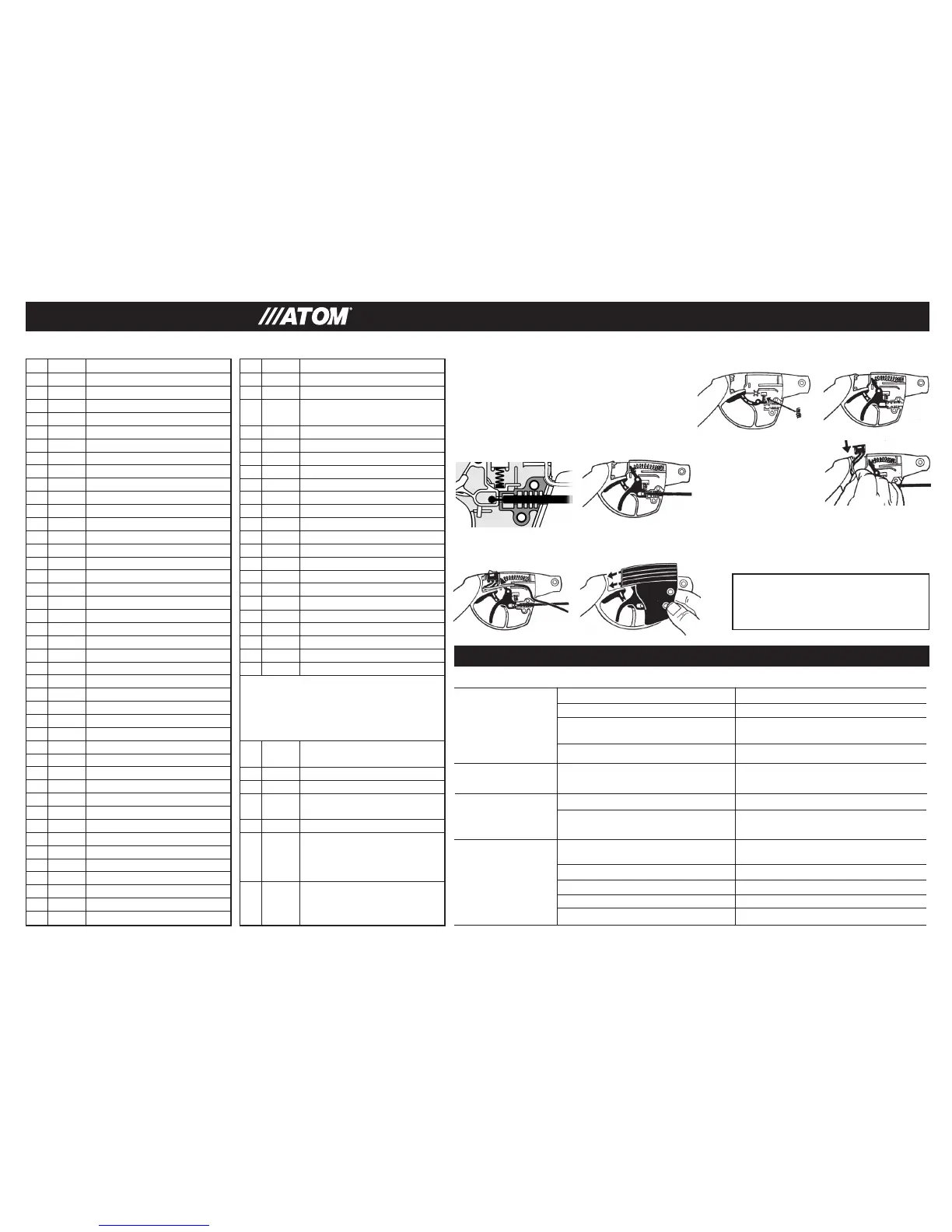
63883A52
THROTTLE TRIGGER AND THROTTLE
INTERLOCK SET
TROUBLESHOOTING TIPS
1. Remove 2 screws and remove cover and all
parts. Re-assemble as follows.
2. Fit throttle inter-lock compression spring (Fig. 29).
3. Fit trigger compression spring then trigger. Front
of Trigger spring fits over retainer post (Fig. 30).
TO REPAIR THROTTLE TRIGGER ASSEMBLY
6. Hold trigger in place with finger until
throttle cover is fitted (Fig. 34). Ensure
throttle cover rear tabs (arrowed engages
underside of handle wall. Screw cover to
handle with 2 screws.
4. Fit throttle cable to position shown for model 430 (Fig. 31)
5. Push switch down into handle switch recess
(Fig.32) Run switch wire through handle (Fig.33).
FIG 34FIG 33
FIG 30FIG 29
FIG 31
FIG 32
LUBRICATION OF GEARS
There is sufficient lubrication to last the
lifetime of the unit.

 Loading...