FIG 14
FIG 15
FIG 18
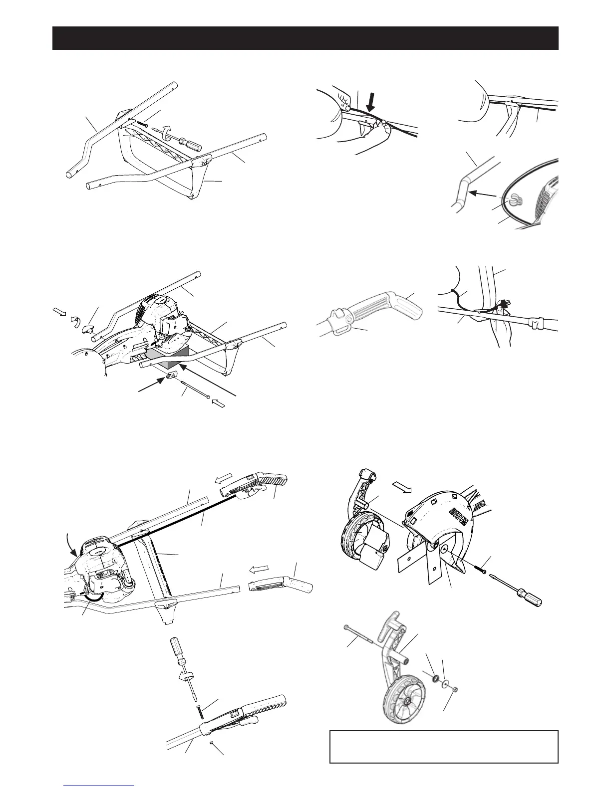
ASSEMBLING HANDLES ON LAWN EDGERS & TILLERS
PAGE 4
FIG 17
TOP VIEW
7
3
10
10
14
1. Using blade screwdriver (or Torx-25 screwdriver). Use M5 x
36mm screws #8 to screw 2 handle tubes #3 & #5 to cross
brace #7. Fig 10.
FIG 10
8
5
7
3
2. Place lawn edger or tiller body on bench or floor. With
approximately 75mm–100mm (3”–4”) spacer under engine.
Fit handle tubes assembled with cross brace #7 to edger or
tiller body as shown with bolt #1 and tighten large plastic
wing nut #6. Fig 11. For professionals, firstly put front ends of
tubes through AV rubbers #7 & #8 in Fig.7 on page 3.
FIG 11
6
1
SPACER
BLOCK
3. Looking down from rear of edger or tiller, feed RH hand grip
#11 with throttle trigger, throttle cable #10 and switch wire
#10 under engine, and over top of cross brace #7 and push
RH trigger hand grip #11 onto end of RH handle tube #5. Fig
12. (Note Electric edgers/Tillers have no (separate) switch
wire). Then also push LH hand grip #13
onto end of LH handle tube #3.
FIG 12
4. Fit and hold M5 loc-nut
#9 (with nylon part of nut
facing away from tube) into
hex recess of hand grip
and insert M5 x 36mm #8
through hand grip (from
other side), through tube
and tightly screw up. Fig 13.
Repeat for other hand grip.
10
5
10
11
3
10
FIG 13
5 9
5. Clip throttle cable #10 and switch wire into place. Fig.14
and 15.
6. Use cable and switch wire C-clip
#14 to retain throttle cable
#10 and switch wire against
RH handle tube #5 adjacent
engine. Fig 16.
7. ELECTRIC EDGERS & TILLERS
Clip cord anchor #12 onto LH handle grip #13 and fit
together onto LH tube #3. Fig 17. Fit screw #8 with nut #9.
Clip power plug cord #14 of motor into place on LH topside
of cross brace #7. Fig 18.
5
14
FIG 16
13
12
8. Fit wheel arm assembly pivot axle #18 into RH side of
main body of machine.
5
7
3
7
8
10
EDGER INSTRUCTIONS CONTINUED PAGE 6
TILLER INSTRUCTIONS CONTINUED PAGE 7
13
NOTE: ARROW TO FRONT
15
18
16
17
24
FIG 20
8(a) Wheel arm without bolt.
On LH side insert M5 x 36mm screw #8 through fixed
encapsulated washer #26, and tighten screw. Fig.19.
8
26
FIG 19
8(b) Wheel arm with
bolt. Insert bolt #15
into wheel arm, and on
LH side fit washer #16
(if washer not already
fitted) and nut #17 onto
protruding bolt. Tighten
nut. Fig.20.
WHEEL ARM ASSEMBLY
18
 Loading...