PAGE 7
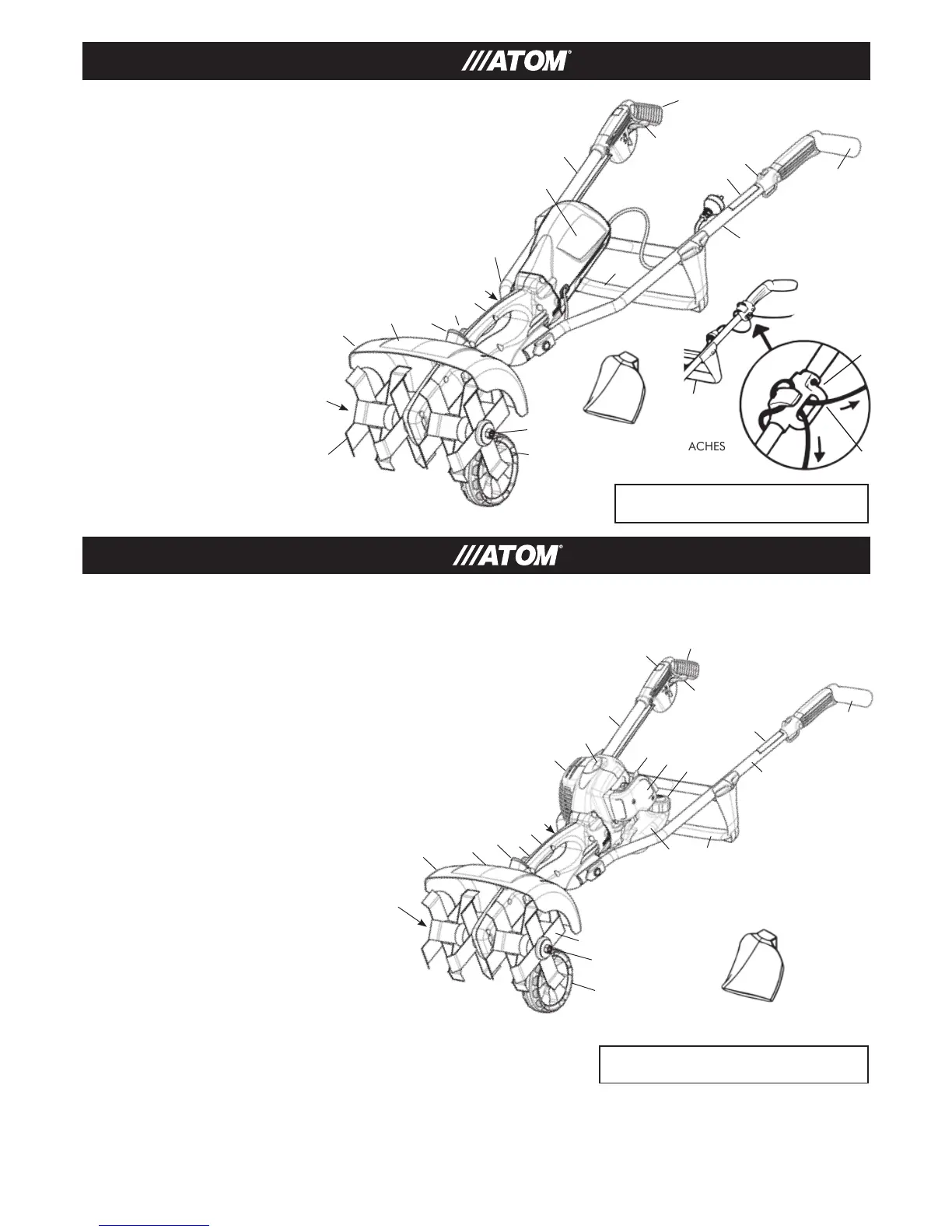
1+2. Each handle grip of the Tiller are held by each hand at all
times during use.
3. The throttle interlock which releases the throttle trigger which
increases speed of engine for automatic safety clutch to
engage and thus rotate tines.
4. RUN/STOP switch.
5. Starter grip of the pull starter which is the device to start the
engine.
6. Handle wing nut for holding handle tubes onto housing.
7. Depth adjustment for adjusting wheel to regulate tine depth.
8. Tine cover reduces the risk of flying debris and direct contact
with the feet or hands.
9. Handle to lift Tiller.
10. Tines rotate when engine speed is increased above idle.
11a. Tine holding nut RH thread (also indicated on
tine cover).
11b. Tine holding nut LH thread (also indicated on
tine cover).
12. Wheel for moving and guiding tiller.
13. Cross Brace, attaches downward on handle tubes.
14. Left and right Handle Tubes.
15. Fuel tank cap, for sealing the fuel tank filler.
16. Fuel Tank.
17. Filter housing covers the air filter element.
18. Muffler reduces exhaust noises and drives gases
away from operator.
19. Spark Plug terminal cap connects the spark plug to
the ignition wire (2-Stroke). On 4-Stroke Honda engine
spark plug is under cylinder cover (1 screw access).
20. Warning label.
21. Fuel pump primer provides additional fuel for a cold start.
22. Lift knob to remove cover.
FIG 44
2
4
14
19
18
3
1
14
15
13
16
5
17
6
9
7
22
21
8
10
11 a
12
1+2.Each handle grip of the Tiller are held by each hand at all times during use.
3. The throttle interlock which releases the throttle trigger which switches on
motor for automatic safety clutch to engage and thus rotate tines.
4. Handle wing nut for holding handle tubes onto housing.
5. Depth adjustment for adjusting wheel to regulate tine depth.
6. Tine cover reduces the risk of flying debris
and direct contact with the feet or hands.
7. Handle to lift Tiller.
8. Tines rotate when motor is switched on.
9a. Tine holding RH threaded nut (also indicated
on tine cover).
9b. Tine holding LH threaded nut.
Also indicated on tine cover.
10. Wheel for moving and guiding tiller.
11. Cross Brace, attaches downward on
handle tubes.
12. Left and right Handle Tubes.
13. Warning label.
14. Lift knob and twist to remove cover.
15. Extension cord anchor.
16. Electric motor pod assembly.
17. Suitable extension cord for outdoor application.
1
2
3
15
13
FIG 43
15
4
7
5
14
13
6
11
10
9a
8
16
PARTS & CONTROLS: ELECTRIC TILLER
PARTS & CONTROLS: GASOLINE TILLER
12
OPTIONAL EXTRA:
FURROW PLOW ATTACHES
TO WHEEL ARM
OPTIONAL
EXTRA:
FURROW
PLOW
ATTACHES TO
WHEEL ARM
12
9b
11b
ELECTRIC TILLER INSTRUCTIONS
CONTINUE ON PAGE 9
GASOLINE TILLER INSTRUCTIONS
CONTINUE ON PAGE 9
20
–
12
–
1
15
11
–
17
17
 Loading...