The UMD-SRB02 Control Box, or Uncontrolled Movement Detector, is a safety system designed for installation with new lifts and retrofitting to existing passenger and goods lifts. It operates in conjunction with bi-directional VG rope brakes (VGRB2) and VG safety gears. The system is engineered to comply with current UKCA and CE requirements, including EMC, Low Voltage, RoHS, WEEE, and specifically EN 81-20:2020 (5.6. Precautions against freefall, excessive speed, unintended car movement, and creeping of the car).
Function Description:
The UMD-SRB02 system monitors lift movement, particularly when the lift doors are open, to detect excessive or uncontrolled car movement. It consists of a movement detector (UMD-SP01) and a controller (UMD-SRB02). The movement detector uses an idler wheel resting on one of the main ropes to sense movement and direction. When the lift doors are open, the system actively monitors for excessive movement. If movement exceeding a predetermined limit (default 150mm, adjustable from 100mm to 900mm) is detected, the controller actuates a safety relay, deploying the brakes or safety gear and sending an emergency stop signal to the main lift control panel by interrupting the main safety circuit. Once deployed, the system requires a manual reset and will not allow the lift to run until the brakes or safety gear are reset.
The control box also continuously monitors the integrity of the connection to the sensor assembly and the status of the rope brakes or safety gear. It performs self-diagnostic tests to ensure all sensors are working. In case of a fault, an ALERT signal is sent to the main lift control panel, requesting the lift to stop at the next floor, open its doors, and go out of service. If a fault is detected while the doors are open, the brakes will be deployed as a fail-safe measure. The system is directly connected to the lift over-speed governor, deploying brakes or safety gear immediately if over-speed is signaled.
A battery backup system ensures continuous operation during power loss. If mains power fails with the doors open, the system continues to monitor movement. If power fails when doors are closed, it will still monitor but allow greater movement before deploying brakes.
Important Technical Specifications:
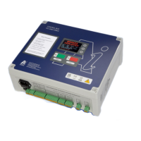
- Control Box (UMD-SRB02): Enclosed in a Polycarbonate/ABS, IP40 rated enclosure, approximately 290mm long x 260mm tall x 120mm deep.
- Movement Detector (UMD-SP01): Fixed, non-contact, non-adjustable type with sealed motion sensors.
- Movement Detection Limit: Predetermined limit of 100mm to 900mm (factory preset to 150mm).
- Electrical Supply Voltage: 230V +/-10%
- Number of Phases: Single Phase, Neutral and Earth
- Frequency: 50/60 Hz
- Full Load Current: 2.0 A
- Normal Running Current: 0.5 A
- Control Box Input Signals: 12V DC 100 mA, requiring a dry/volt-free relay contact (normally open and energized when doors are closed).
- Over-speed Governor Connection: Directly to the normally closed (when not in over-speed condition) over-speed governor switch.
- Output Signals (Alert/Emergency Stop): Dry/volt-free relay contacts, 230 Volts maximum, not exceeding 2 amps.
- Fuses: F1 = Internal Power Supply 500mA (for 240V supply) or 800mA (for 110V supply); F2 = Control voltage 2.0Amps (12V DC). All fuses are 5mm diameter x 20mm long glass fuses (SIBA manufactured).
- Battery Backup: Maintains brakes for 10-20 minutes during mains power loss.
Usage Features:
- Visual Display Screen: Provides system status messages and assists with fault finding.
- Resetting the System: Manual reset required after brake deployment. Involves pressing a green reset button, confirming, and manually resetting brakes/safety gear.
- Bypassing the System (Engineer Maintenance Control): Allows disabling movement detection for testing/maintenance. If over-speed or free fall occurs, brakes/safety gear still deploy. This mode is active for 1 hour, then reverts to normal running. Accessed via Menu > Mode Select > By-Pass.
- Test Deployment of Brakes: Procedure to test brake deployment, which also sends an emergency stop signal to the main lift panel. Accessed via Menu > Engineer mode (pass code 554) > Red test button > Static test.
- Hand Winding Instructions: Specific steps for re-engaging drop jaws and hand-winding the machine after brake deployment.
- Fail-Safe Design: The system is designed to be fail-safe; any cable breakage or over-speed will result in brake deployment.
Maintenance Features:
- Controller Maintenance:
- Monthly: Ensure exterior is clean, dry, and dust-free.
- 6 Monthly: Check fuse ratings, cable entry points, and cable strain relief.
- 12 Monthly: Check control voltage (12V-14.5V DC). Test battery charge (should be at least 12.2V on battery; replace if it doesn't hold charge after 12 hours).
- 36 Monthly: Replace battery.
- Movement Detector Assembly Maintenance:
- Monthly: Check pulley cleanliness, clear debris/dust.
- 6 Monthly: Check all moving parts for free movement and wear, rope alignment, excessive wear, bearings for play/end float. Lubricate springs if necessary. Check security of all parts, nuts, and bolts.
- Operational Checks (12 Monthly):
- Verify correct functioning of Test/Run/Reset/Bypass modes.
- Check electric safety devices.
- Check brake deployment.
- Test error signals by removing encoder cable connection and checking screen message.
- Check movement detector by opening doors and moving idler wheel through 1 revolution to trigger brake deployment.
- General Advice: Installation, commissioning, and maintenance should only be carried out by authorized "Competent Persons" who have received necessary instruction and training. No alterations, modifications, or repairs without written consent from Atwell International. Use only specified or supplied replacement parts.
- Safety Notes: Always isolate main supply before opening the control box. Potentially live connections exist even when fuses are withdrawn. Do not tamper with the control box program; unauthorized attempts will void warranty and responsibility.