4 Atwell International Limited
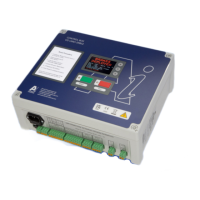
The movement detection control panel is designed to be installed with new lifts
and retrofitted to existing passenger and goods lifts and used in conjunction with
the bi-directional VG rope brake (VGRB2) and VG safety gears.
It has been designed and constructed to comply with all current UKCA and CE
requirements, i.e. EMC, Low Voltage, RoHS, WEEE and more specifically to meet the
requirements of EN 81-20:2020 (5.6. Precautions against freefall, excessive speed,
unintended car movement and creeping of the car).
The movement detection controls connect to the main lift control panel. From
here it can receive power and signals to tell if the lift doors are open, or that the lift
over speed governor is operating correctly. It also sends signals to the lift to stop
the lift at the next floor when a fault is detected.
The system will always deploy the brakes or safety gear immediately and interrupt
the main lift safety circuit if over-speed is signalled.
The movement detector monitors movement by looking at an idler wheel resting
on one of the main ropes. As the rope moves so does the idler wheel, and as the
idler wheel rotates the movement and direction of movement is detected.
When the doors are open the system is checking for excessive movement. If
excessive movement is detected then the brakes or safety gear, under its control
will be deployed and in addition to this, an emergency stop signal will be sent to
the main lift control panel, by means of interrupting the main safety circuit.
There are other functions included within the system such as an indication of
status to assist fault finding, resetting of the brakes, manual override to test the
deployment of the brakes, ability to bypass the system (allowing car top control,
without deploying the rope brakes) and pit safety to monitor car movement when
engineers are in the lift shaft or pit.
Power loss is catered for by the incorporation of an internal battery backup system
to seamlessly switch from mains power to battery and back again without the
need for manual intervention to reset the brakes or safety gear. But if during the
power loss excessive movement occurs, or the overspeed governor trips, the
brakes or safety gear will be deployed and a full reset will be required.
If during its normal operation, the system develops a fault then an error or alert
signal will be sent requesting the lift stops at the next floor, doors opened, and
stays there until the fault is corrected. During this time whilst the doors are open
the system will continue to monitor excessive movement.
Overview