9UMD-SRB02 Version 1
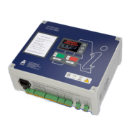
Indication of the system status will be provided by messages displayed in the
controller window
In addition to this a small visual display shows a text interface explaining the status
and warnings.
Signals
Controller input power supply will be 230V or 110V AC 50/60Hz, it has an internal
12v DC control voltage, power supply and battery backup.
The system requires the following signals and connections to the external contacts
to enable it to operate.
1. A car Door Open / Closed Input signal.
2. A landing Door Open / Closed Input signal.
These inputs should be a connected to a Dry / volt free, normally open, pair of relay
contacts wired parallel. It only requires a maximum switching current of 0.25A 12V
DC.
3. An over speed OK signal, normally closed when no over speed, opens when
lift is over speeding.
Please note if the lift loses mains power the above door signals will open, therefore
the third signal we need must be connected directly to the over speed governor
switch, as if this signal opens the brakes will be immediately deployed.
Output signals from the controller will be volt free relay contacts. The contacts are
rated for up to 2 Amp Max at 250VAC. These are:-
4. Main Lift Safety Circuit Output Signal.
5. Main Lift Alert Output Signal
If replacing the safety circuit fuse it must be a slow blow 2 Amp fuse (Part No. little
fuse 0215002 MXEP)


 To Next Page