WARNING
CARBON MONOXIDE POISONING
Properly seal vent assembly to prevent carbon monoxide from entering
coach.
DO NOT draw combustion air from living area.
DO NOT vent exhaust air into the living area or an enclosed porch.
WARNING
CARBON MONOXIDE POISONING
Furnace must be installed and vented to these instructions.
Improper installation, adjustment, alteration, service or
maintenance can cause injury or property damage.
Improper installation location may cause furnace to produce negative
pressure, affecting combustion air or venting of other appliances.
WARNING
CARBON MONOXIDE POISONING
Properly seal door to prevent carbon monoxide from entering
coach.
Properly adjust draft cap to prevent carbon monoxide from
entering coach.
Contents
SPECIFICATIONS ................................................................... 2
MODEL Table 1 ............................................................................. 2
DUCTING CONFIGURATION Table 2 ........................................... 2
DIMENSION Table 3 ..................................................................... 2
MINIMUM CLEARANCE TO COMBUSTIBLES: Table 4 .............. 2
INSTALLATION AND SAFETY CODES.................................. 3
GENERAL FURNACE LOCATION AND INSTALLATIONS ... 3
FURNACE INSTALLATION ..................................................... 3
WALL CUTOUTS Table 5 ............................................................. 3
SMALL VENT INSTALLATION ................................................................ 3
STANDARD DOOR INSTALLATION ....................................................... 4
INTERIOR GRILL INSTALLATION .......................................................... 4
FLEXIBLE DUCTING SYSTEMS .............................................................. 5
PROPANE GAS CONNECTION .............................................. 5
ELECTRICAL CONNECTIONS ............................................... 5
THERMOSTAT INSTALLATION ............................................. 6
OPERATING INSTRUCTIONS ................................................ 6
WIRING AND LADDER DIAGRAM .......................................... 7
PART DRAWINGS & PART LISTS ......................................... 8
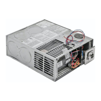
SPECIFICATIONS
MODEL Table 1
(WC = WATER COLUMN)
DUCTING CONFIGURATION Table 2
DIMENSION Table 3
Furnace 21 lbs
Boxed 24 lbs
MINIMUM CLEARANCE TO COMBUSTIBLES: Table 4
Floorboards, walls & similar combustible building materials
must be provided the full length and width of the unit.
Spacing of 1/4” to ducting within 3 feet of furnace must be provided
unless UL listed wire bound vinyl ducts are used. All ducting material
must be rated for continuous use at minimum of 200°F.
Clearances are specifically for plywood or similar building materials
surrounding the furnace (i.e. Furnace should not be located under
furniture or in a closet space where clothing or other material could be
located).
Furnace efficiency rating is a thermal rating determined under
continuous operating conditions, independent of any installation.
Efficiency rate is given at 76% minimum; actual efficiency rating may
be higher.
Return air is supplied through openings or around the furnace. All
return air passages must be kept clear for furnace to function properly.
Refer to Minimum clearance to floorboards, walls & similar combustible
building material in Table 4.
The total unobstructed return air opening size must not be less than
specified in specification Table 1. Failure to meet minimum return air
requirements nullifies furnace warranty.
To install without adding the additional 16 sq. in. cutout on the blower
side supply the right side of unit (blower side) with 2” clearance full
length of the unit.
 Loading...