Installation Steps
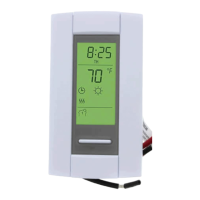
n Connect the rear thermostat wires (FIGURE 1) to the power
and to the load using solderless connectors for copper wires.
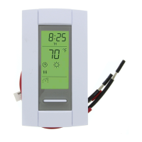
Connecting the floor sensor (Figure 2)
• Insert the probe into one of the two holes available below
the terminal board and connect the wires to terminals 3
and 4 (no polarity needs to be respected).
• The cable must run on the left side of the cavity located on
top of the terminal board, outside the electrical box and
follow the wall down to the floor.
The temperature sensor wire cannot cross any heater
wires and must NOT be directly on or adjacent to a heating
wire. For maximum performance, the sensor probe should
be centered between the wires in the mat.
Connecting the remote input (Figure 2)
• Insert the remote cable (use an 18 to 22 gauge flexible
wirecable) into one of the two holes available below the
terminal board and connect CT240 terminals 1 and 2 to
PB112 terminals 1 and 2 respectively.
• The cable must run on the left side of the cavity located on
top of the terminal board and outside the electrical box.
o Push the excess wire (except for the probe/remote) back into
the electrical box to prevent interference with the thermostat.
p Secure the thermostat using two (2) screws. Once the
thermostat is properly installed, return power to heating
system.
PB112
Installation Instructions
For models: 120GA / 120GB / 120S /
240GA / 240GB / 240D / 240S / 277S / 347S
Material
n One (1) power base
o Two (2) screws
p Four (4) solderless connectors for copper
wires
NOTE: Special CO/ALR solderless connectors must be used
when connecting with aluminum conductors.
q One (1) floor sensor and one (1) flat tip screwdriver (for GA and
GB models only)
Installation Guidelines
Turn off power to the heating system at the main power panel to
avoid electrical shock. Installation should be carried out by an
electrician.
High voltage thermostats must be installed onto an electrical
box.
For a new installation, choose a location about 5 ft. above the
floor.
The thermostat must be installed facing the heating system.
The thermostat must be installed on an inside wall.
Avoid locations where there are air drafts (top of staircase, air
outlet), dead air spots (behind a door), direct sunlight or con-
cealed chimneys or stove pipes.
AUBE TECHNOLOGIES INC. ONE (1) YEAR LIMITED WARRANTY
This product is guaranteed against workmanship defects for a one year period
following the initial date of purchase. During this period, AUBE Technologies Inc. will
repair or replace, at our option and without charge, any defective product which has
been used under normal conditions. The warranty does not cover delivery costs and
does not apply to products poorly installed or randomly damaged following installation.
This warranty cancels and replaces any other manufacturer's express or implied
warranty as well as any other company commitment. AUBE Technologies Inc. cannot
be held liable for related or random damages following the installation of this product.
The defective product as well as the purchase invoice must be returned to the place of
purchase or mailed, prepaid and insured, to the following address:
Aube Technologies Inc.
705 Montrichard
Saint-Jean-sur-Richelieu, Quebec, Canada J2X 5K8
If you have any questions concerning the installation of the
PB112 power base, call our technical support team at:
Phone: Montreal area: (450) 358-4600
Canada / U.S.: 1-800-831-AUBE (2823)
Fax: (450) 358-4650
Email: service@aubetech.com
Monday to Friday from 8:30 AM to 5:00 PM EST.
For more information on our products, visit us at:
www.aubetech.com
Technical Specifications
Storage: -4°F to 120°F (-20°C to 50°C)
GFCI: GA = 5 mA, GB = 30 mA trip level
Remote input: Dry contact
Size (H•W•D): 124 x 70 x 23 mm (4.89 x 2.76 x 0.91 in)
Certifications:
Model Supply Max. Load Power
Conn.
a
a. Connection type: 4w = 4 wires, DP = Double Pole, SP = Single Pole
GFCI
120GA 120 VAC, 60Hz 15 A 1800 W 4w/DP 5 mA
120GB 120 VAC, 60Hz 15 A 1800 W 4w/DP 30 mA
120S 120 VAC, 60Hz 20 A 2400 W 4w/SP
240D 240 VAC, 60Hz 15 A 3600 W 4w/DP
240GA 240 VAC, 60Hz 15 A 3600 W 4w/DP 5 mA
240GB 240 VAC, 60Hz 15 A 3600 W 4w/DP 30 mA
240S 240 VAC, 60Hz 20 A 4800 W 4w/SP
277S 277 VAC, 60Hz 15 A 4155 W 4w/SP
347S 347 VAC, 60Hz 15 A 5205 W 4w/SP
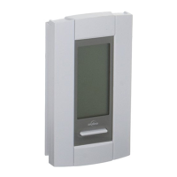
Introduction
The PB112 power base is designed to power a TH11x Series control
module.
Refer to the technical specifications for maximum resistive load.
R
CUS
Models:
120 GA / GB
240 GA / GB
Models:
120S / 240S
240D / 277 / 347S
R
CUS
04/08/2003 920-112-002-00-1-A
Figure 1
Figure 2