- 20 -
the outside surface. Cables should come from the outside surface to the inside. You need
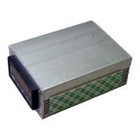
to fit the cables through the grommet one at a time. See Fig 24.
Fig 24. Feed cables through the back panel of controller box.
4) Feed the cables through the controller box BEFORE connecting them to the controller as
shown in Fig 25.
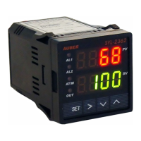
Fig 25. Wiring of the controller.
Wiring the controller correctly is a very critical step. Failure to install it correctly can cause
damage to the machine and electric shock. The terminal numbers are printed on the labels
located on both sides of the controller. Table 1 shows wiring to the controller terminals. The
brown-colored power cable needs to be connected to terminal 1. The black-colored power
cable needs to be connected to terminal 2. The SSR input cable has a polarity. The red-
colored cable is for terminal 10. Two white-colored cables, one for SSR input and one for
steam control are connected to terminal 9. The blue-colored steam control cable connects to
terminal 3. The RTD cable needs to be connected to terminals 7 and 8. The white-colored
RTD jumper cable needs to be connected between terminals 6 and 7. The black-colored
jumper cable needs to be connected between terminals 2 and 4. The green-colored cable
needs to be connected to terminal 5. See Fig 26. Bending the wire tip will make the insertion
 Loading...