- 9 -
getting damaged, install the sensor without unwrapping the cable (i.e., install it the way it
was received as shown in Fig 6). This will reduce any twisting and pulling force acting
on the sensor while screwing it into place. The sensor does not need to be very tight.
Finger tight is OK. [NOTE: If you want to make sure the sensor didn’t get damaged
during installation, you can measure the resistance of the sensor after installation. It
should be in the 100 to 110 ohm range at room temperature.].
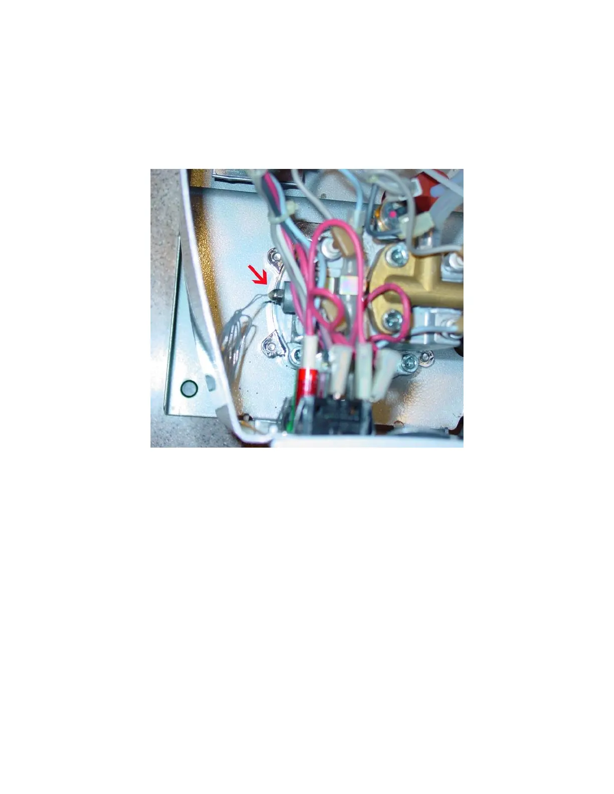
Fig 17a. The red arrow shows the RTD sensor after installation (Gaggia Coffee, instead of
Gaggia Classic, is in the picture because the sensor mounting site is easier to show)
2) Install SSR output cable. One cable from the SSR output (one of the two thick red
wires from SSR) needs to be connected to the cable connector that was on the brew water
thermostat (red arrow in Fig 17b). The other cable from the SSR output need to be
connected to the gray cable connector that was on the steam thermostat (red arrow in Fig
17c and Fig 17d). In other words, one SSR output cable goes to the cable from the brew
thermostat, the other SSR output cable goes to the cable from steam thermostat.
 Loading...