AUBER INSTRUMENTS
Instruction Manual
11. Error Message and trouble shooting
11.1 Display EEEE
This is an input error message. The possible reasons are, the sensor is not
connected correctly; the input setting is wrong type; or the sensor is defective.
If this happens when using thermocouple sensor, you can short terminals 9
and 10. If the display shows the ambient temperature, the thermocouple is
defective. If it still displays EEEE, check the input setting, Inty, to make sure it
is set to the right thermocouple type. If Inty setting is correct, the controller is
defective. For RTD sensor, check the input setting first because most
controllers are shipped with input set for thermocouple. Then check the wiring.
The two red wires should be on terminals 9 and 10. The clear wire should be
on terminal 8.
11.2 No heating
When controller output is set for relay output, the “AL2” LED is synchronized
with output relay. When controller output is set for SSR output, the “OUT” LED
is synchronized with SSR control output. If there is no heat when it is
supposed to, check the AL2 or OUT first. If it is not lit, the controller parameter
setting is wrong. If it is on, check external switching device (if the relay is
pulled-in, or the red LED of the SSR). If the external switching device is on,
then the problem is either the external switching device output, its wiring, or
the heater. If the external switching device is not on, then the problem is either
the controller output, or the external switch device.
11.3 Poor Accuracy
Please make sure calibration is done by immersing the probe in liquid.
Comparing with reference in air is not recommended because response time
of sensor depends on its mass. Some of our sensor has response time >10
minutes in the air. When the error is larger than 5°F, the most common
problem is improper connection between the thermocouple and the controller.
The thermocouple needs to be connected directly to the controller unless a
thermocouple connector or an extension wire is used. A copper connector,
copper wire, or thermocouple extension wire with wrong polarity connected on
the thermocouple will cause the reading drift more than 5°F.
6
7
8
910
11
12
13
14
1
2
3
45
J2
+
-
K type TC
-
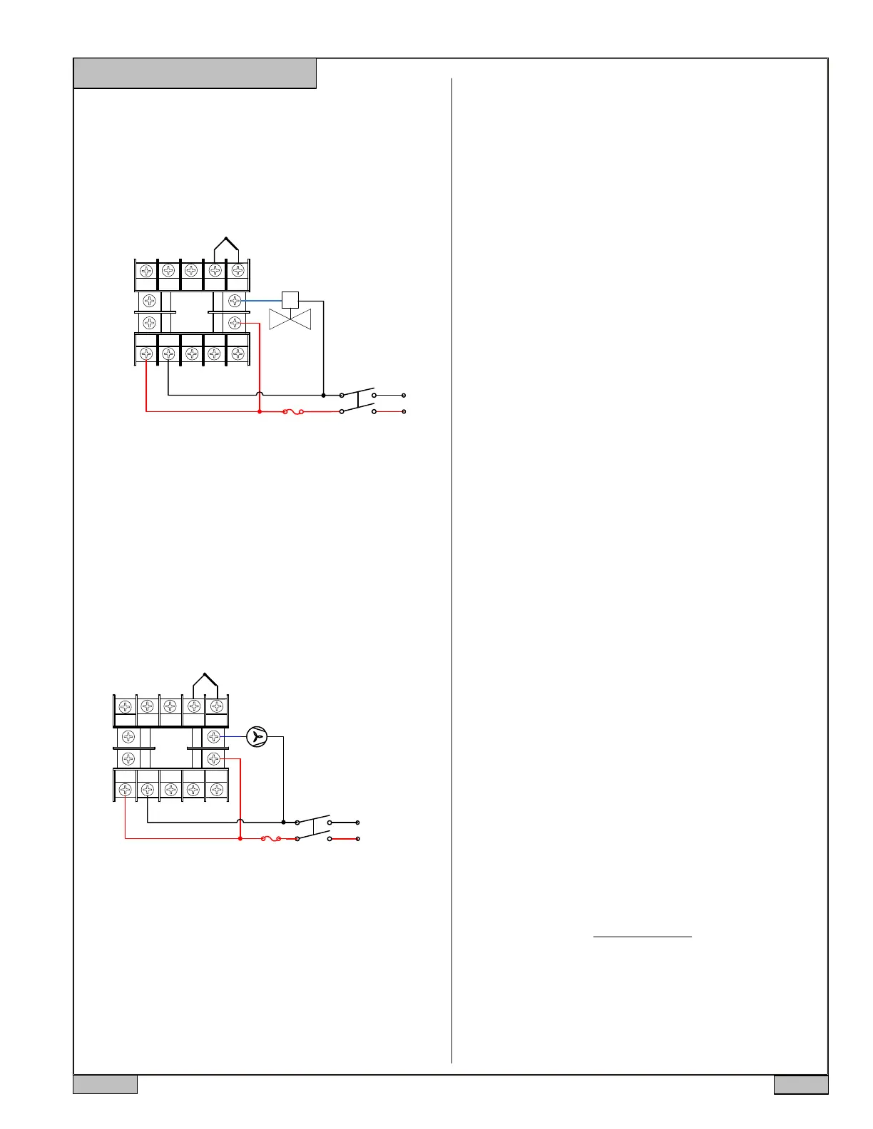
10.2 A 24V DC solenoid valve is switched by J2 relay in On/off mode. The
valve will be on until temperature reaches 105 °F. Then, it will shut off. When
the temperature drops to below 100 °F, it will be on again. The power source
is 24V DC. A K type thermocouple is used as the temperature sensor.
a. Wiring diagram
Figure 11. Typical wiring set up for a 24V gas, hot water valve, or
a contractor with 24V coil voltage
S
Solenoid valve
b. Parameter setting. These are the parameters that need to be changed
from the initial value: outy=4 for On/Off mode with J2 relay output; Hy =5
degree, SV=105 °F for the target temperature.
24V DC
10.3 A BBQ smoker needs to be controlled at 200°F. The power source is
12V DC. A K type thermocouple is used as the temperature sensor. The
system consists of a 12V DC fan, a K type thermocouple.
Figure 12. Typical wiring for BBQ smoker temperature control
b. Parameter setting. These are the parameters that need to be changed
from the initial value: outy=1 for PID mode with relay output; ot=1 0, the
reason we set the cycle time at 1 0 is that the fan needs time to start;
SV=250 °F for the target temperature. Following are the tuning parameters
that we found work best for this type of application. P=1.2, I=300, d=70,
SouF=0.7
2018.07
P5/5
+
6
78
910
11
12
13
14
1
2
3
45
J2
+
-
K type TC
+
-
Fuse
12V DC
a. Wiring diagram
Fan
Fuse
Auber Instruments
5755 North Point Parkway, Suite 99
Alpharetta, GA 30022
www.auberins.com
e-mail: info@auberins.com Tel: 770-569-8420
Copyright 2007-2018, Auber Instruments All Rights Reserved.
No part of this manual shall be copied, reproduced, or transmitted in any
way without the prior, written consent of Auber Instruments. Auber
Instruments retains the exclusive rights to all information included in this
document.
 Loading...