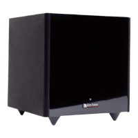
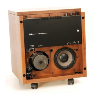
1. TECHNICAL DESCRIPTION
The theoretical Background for the Ace-Bass principle used in
Subwoofer B2-50 is described in AES Preprint #1381.
The functions described below are separated by dotted lines
on the Circuit Diagram.
1.1 Power Supply
The primary of the power transformer is always connected
to the power cord via a voltage selector and a power fuse (5.0A
slow at 117 V, 2.5A slow at 220-250 V). The idle current in this
transformer is very low (approx. 25mA at 117 V supply).
The center tapped secondary winding supplies the Automatic
ON/OFF via two diodes D201, D202, and a double rectifier D101
via a DPST switch K101. This switch is operated by a relay in
the Automatic ON/OFF circuits.
Rectifier D101 supplies +- 40 V to the Power Amplifier, and also
stabilized +- 15 V via voItage regulators, V101, V103.
It is very important that the -15 V tracks the +15 V accurately
when power is switched on or off. Mistracking can cause transients
or oscillations in the electronic circuits.
To maintain tracking of the +15 V and -15 V when power is
disconnected, the +40 V must decay faster than the -40 V.
For this reason the Power Amplifier is built to always maintain
a small positive offset voltage (10-100mV) on its output terminals
under operating conditions.
If the B2-50 is tested without any load on the Power Amplifier,
or with fuses F501, F502 removed, the balance between +15 V and
-15 V may be upset during on/off switching. In such cases the
operational amplifiers may start oscillating when power is dis-
connected, so that Automatic ON is actuated. This is normal under
these conditions, and the electronics will not be damaged.