ATW-T1006 and ATW-T1007 Installation and Operation
3
Installation
Transmitter Location
For best operation the ATW-T1006 boundary microphone transmitter
or ATW-T1007 microphone desk stand transmitter should be kept at
least 6' (2 m) from the System 10 receiver to help assure maximum RF
performance.
Power Connection
NOTE: Use only the supplied AC adapter and power cord to power or
charge the boundary and desk stand transmitters. To use AC power,
connect the power cord’s USB A-type male port to the AC adapter and
connect the Micro-USB B port to the USB Power Input on the rear of
the transmitter. Next, plug the adapter into a standard 120 V 60 Hz or
230 V 50 Hz (depending on global location) AC power outlet. The AC
adapter and USB cable also charges the transmitter’s internal battery.
Charge battery in an environment with moderate temperature (41°F –
95°F). The system will not charge in temperatures below 32°F or above
104°F in order to prevent potential damage to battery. For safety and to
conserve energy, unplug the AC adapter from the AC outlet when the
system is not in use. Store transmitter in a cool place.
ATW-T1006 Boundary Microphone Transmitter and
ATW-T1007 Microphone Desk Stand Transmitter
Controls and Functions
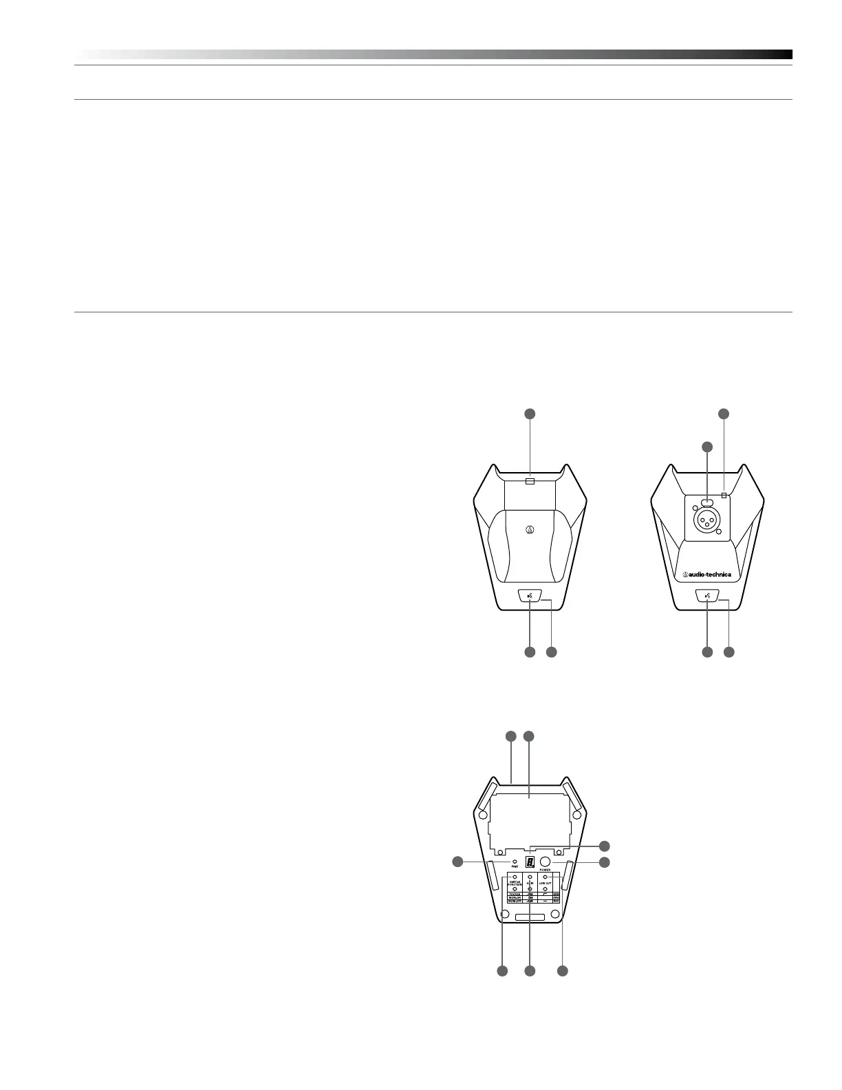
Figure A—ATW-T1006 and ATW-T1007 (Top)
1. User Switch: Depending on switch function setting, press to toggle
talk/mute, press to talk or press to mute.
2. LED 1: Indicates transmitter status: power on/off, mute/talk, battery
low/charging. See LED chart on page 4.
3. LED 2: Indicates transmitter status: power on/off, mute/talk, battery
low/charging. See LED chart on page 4.
4. 3-Pin XLRF-type Input (ATW-T1007 only): Use to mount any
gooseneck microphone with an XLRM-type output
Figure A ATW-T1006 ATW-T1007
Figure BFigure B—ATW-T1006 and ATW-T1007 (Bottom)
1. Battery Compartment
2. Pairing Switch: Press to complete pairing sequence. See page 5.
3. System ID Display: Shows System ID. See page 5.
4. Power Switch: Press and hold to turn receiver on or off.
5. Switch Function: Press to change functioning of User Switch
6. Gain Control: Press to change input gain level.
7. Low-Cut Switch: Press to turn low-cut lter on or off.
8. Power Input: Connect the AC Power Supply adapter included in
the system to charge/operate the transmitter.
2 21 1
3 3
4
18
2
3
4
6 75
 Loading...