page 1 – 4
AIR 1 / Dec 2007
INSTALLATION AND POWER
Audio and Control Wiring
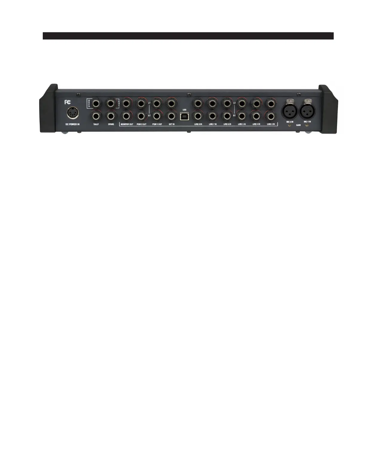
All audio I/O connections to the AIR 1 console are made via TRS and XLR connec-
tors located on the rear panel of the console, except for the USB connection.
Two XLR female connectors are provided to bring balanced mono microphone level
signals into the console for control by the rst two (microphone) faders. These XLR
connectors are wired “pin 2 hot.”
Six pairs of TRS (Tip-Ring-Sleeve) jacks are provided to bring balanced stereo line
level signals into the console for control by (line) faders three through eight. The high
side of the balanced line is wired to the tip (T), the low side of the balanced line is on
the ring (R), and the sleeve (S) is connected to the console ground. The tip and ring are
automatically switched to ground when there is no matching plug inserted in the jack.
One pair of TRS jacks is provided to bring an additional stereo line level signal into
the console for use by the monitor circuits. These are also wired with the tip high, the
ring low, and the sleeve ground, and with automatic grounding when no plug is inserted.
Two pairs of TRS jacks are provided to bring the two stereo program outputs (PGM 1
and PGM 2) out of the console as balanced line level +4dBu signals. The tip is high,
the ring is low, and the sleeve is ground.
One pair of TRS jacks is provided to bring the stereo monitor output out of the
console as separate (left and right) unbalanced line level signals at a nominal level of
-2dBu (equivalent to one side of a balanced +4dBu output). The tip is high and both
the ring and the sleeve are connected to ground.
One TRS jack is provided to bring the mono cue out of the console as an unbalanced
line level signal (nominal -2dBu). The tip is high and both the ring and the sleeve are
connected to ground.
One TRS is provided for the operator to plug in a set of headphones. This is wired
as a standard headphone jack, with the left signal on the tip, the right signal on the ring,
and the sleeve connected to ground.
One TRS jack is provided to hook up an interface to an Air Tally light. This output
comes from a set of relay contacts and is designed to switch a low DC voltage (30 VDC
maximum) at a moderately low current (2 ADC maximum) to activate a DC light, or to
activate an external DC relay which can then be used to activate an AC operated light.
Never bring AC power into the console on this or any other connector. The relay
normally open (N.O.) contact appears on the tip and the common contact appears on
the ring. The sleeve is connected to ground.
One remaining TRS jack on the rear panel is not used.
The USB port uses the type B connector in the center of the rear panel for interfac-
ing with a computer (see page 2-7 for details).
A 5-pin DIN connector is provided to accept console power from the external power
supply.
AIR 1 / Mar 2012
 Loading...