page 1 – 5
AIR 1 / Dec 2007
INSTALLATION AND POWER
Unbalanced Connections (analog audio)
ANALOG INPUTS – Wire to the console with typical shielded two conductor cable
(like Belden 9451), just as if you were connecting a balanced source. At the unbalanced
source machine’s output, connect the black wire (LO) to the shield.
ANALOG OUTPUTS – The AIR 1 console’s PGM 1 and PGM 2 line level analog
outputs are electronically balanced, low impedance, outputs, expecting a minimum load
of 600 ohms. The outputs are balanced but are not oating. Therefore, care must be
exercised when connecting them to an unbalanced system. While temporarily short-
ing the low side of the output signal to ground will not cause any problems, continued
operation under these conditions will result in increased distortion, decreased reliability,
and possible oscillation problems. If you must connect one of these outputs to an
unbalanced system, be sure to leave the low side unterminated, and connect the
unbalanced system to the high side output and shield connections only.
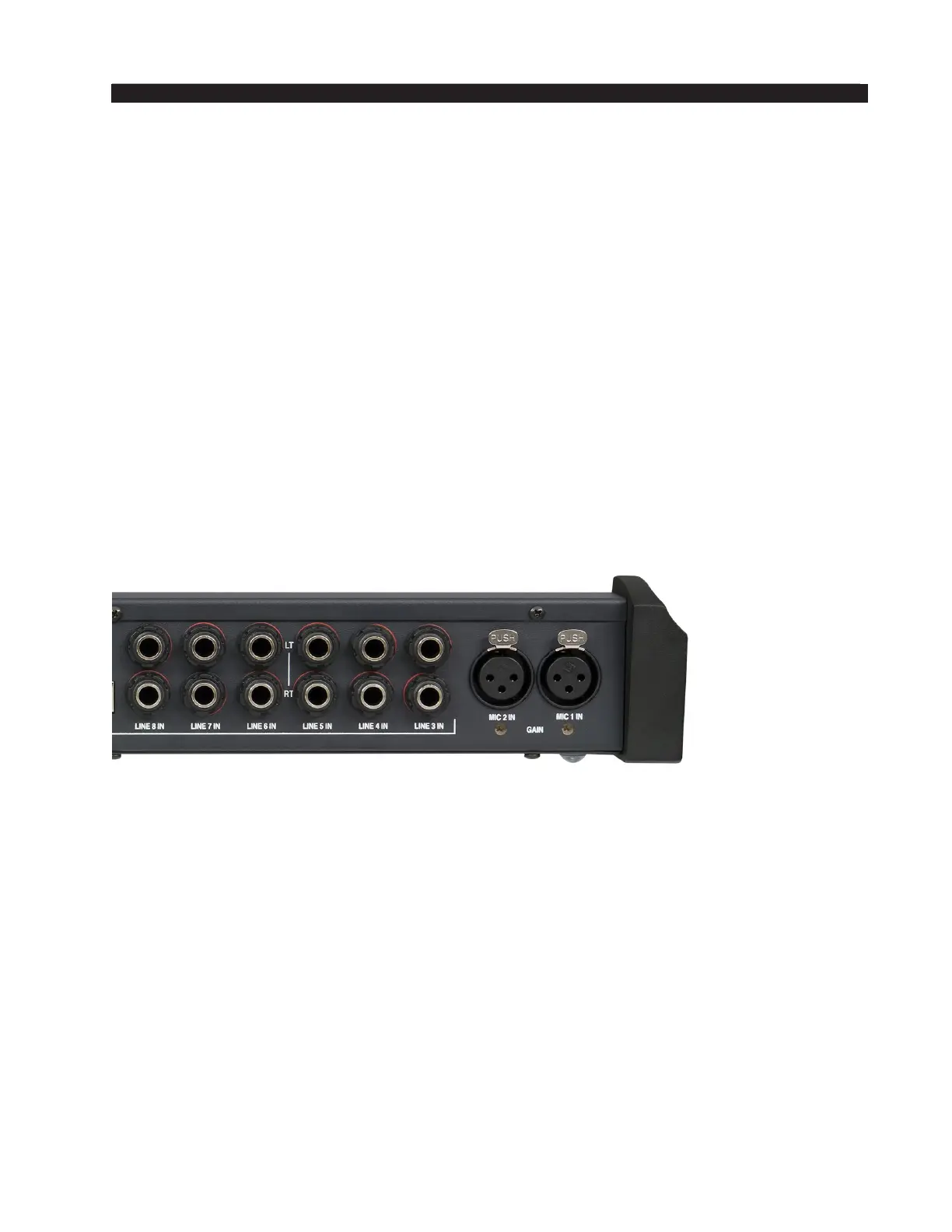
Hook-Ups
The rear of the console has multiple TRS connectors to plug in 6 stereo line inputs
and the external input, as well as providing program 1 and 2, monitor, cue, headphone,
and tally output connections. There are also two female XLR connectors provided for
microphone MIC 1 and MIC 2 inputs.
MIC 1 and MIC 2 Inputs
All signals are analog mono. The mic input level is normally -50dBu balanced.
PIN 1 XLR 1 SH – MIC 1 IN SH
PIN 2 XLR 1 HI – MIC 1 IN HI
PIN 3 XLR 1 LO – MIC 1 IN LO
PIN 1 XLR 2 SH – MIC 2 IN SH
PIN 2 XLR 2 HI – MIC 2 IN HI
PIN 3 XLR 2 LO – MIC 2 IN LO
LINE 3 IN through LINE 8 IN
The top TRS jack (TRS 1) is LEFT and the bottom TRS jack (TRS 2) is RIGHT for
each channel. All signals are analog stereo, +4dBu balanced.
TRS 1 TIP – LINE X LEFT HI
TRS 1 RING – LINE X LEFT LO
TRS 1 SLEEVE – LINE X LEFT SH
TRS 2 TIP – LINE X RIGHT HI
TRS 2 RING – LINE X RIGHT LO
TRS 2 SLEEVE – LINE X RIGHT SH
AIR 1 / Mar 2012
 Loading...