Page 3 - 15
R-60 / Nov 1994R-60 / Nov 1994
R-60 / Nov 1994R-60 / Nov 1994
R-60 / Nov 1994
CC
CC
C
ONSOLEONSOLE
ONSOLEONSOLE
ONSOLE
L L
L L
L
OGICOGIC
OGICOGIC
OGIC
& I/O C & I/O C
& I/O C & I/O C
& I/O C
ONNECTIONSONNECTIONS
ONNECTIONSONNECTIONS
ONNECTIONS
LS-60 Inputs 5 & 6LS-60 Inputs 5 & 6
LS-60 Inputs 5 & 6LS-60 Inputs 5 & 6
LS-60 Inputs 5 & 6
(CT1, LS-60 load sheet dwg)
Pin 1 - LINE 6 LEFT INPUT, SHIELD
Pin 2 - LINE 6 LEFT INPUT, LOW
Pin 3 - LINE 6 LEFT INPUT, HIGH
Pin 4 - LINE 6 RIGHT INPUT, SHIELD
Pin 5 - LINE 6 RIGHT INPUT, LOW
Pin 6 - LINE 6 RIGHT INPUT, HIGH
Pin 7 - LINE 5 LEFT INPUT, SHIELD
Pin 8 - LINE 5 LEFT INPUT, LOW
Pin 9 - LINE 5 LEFT INPUT, HIGH
Pin 10 - LINE 5 RIGHT INPUT, SHIELD
Pin 11 - LINE 5 RIGHT INPUT, LOW
Pin 12 - LINE 5 RIGHT INPUT, HIGH
LS-60 OutputLS-60 Output
LS-60 OutputLS-60 Output
LS-60 Output
(CT4, LS-60 load sheet dwg)
Pin 1 - LEFT OUTPUT, SHIELD
Pin 2 - LEFT OUTPUT, LOW
Pin 3 - LEFT OUTPUT, HIGH
Pin 4 - RIGHT OUTPUT, SHIELD
Pin 5 - RIGHT OUTPUT, LOW
Pin 6 - RIGHT OUTPUT, HIGH
Pin 7 - AUDIO COMMON
Pin 8 - NO CONNECTION
Pin 9 - NO CONNECTION
Pin 10 - AUDIO COMMON
Pin 11 - NO CONNECTION
Pin 12 - NO CONNECTION
Tape Remote Switches 1-3Tape Remote Switches 1-3
Tape Remote Switches 1-3Tape Remote Switches 1-3
Tape Remote Switches 1-3
(CT1-CT14, R-60 Mother Board load sheet dwg)-
(CT1-CT6, R-60 Ext Mother Board load sheet dwg)
Pin 1 - SWITCH 1, LED CATHODE
Pin 2 - SWITCH 2, LED CATHODE
Pin 3 - SWITCH 3, LED CATHODE
Pin 4 - SWITCH 1, LED ANODE
Pin 5 - SWITCH 2, LED ANODE
Pin 6 - SWITCH 3, LED ANODE
Pin 7 - SWITCH 1, COMMON
Pin 8 - SWITCH 2, COMMON
Pin 9 - SWITCH 3, COMMON
Pin 10 - SWITCH 1, NORMALLY OPEN
Pin 11 - SWITCH 2, NORMALLY OPEN
Pin 12 - SWITCH 3, NORMALLY OPEN
USER NOTE: USER NOTE:
USER NOTE: USER NOTE:
USER NOTE: The 1K ohm series
resistors on the TR-60 card have been
selected to allow a wide range of oper-
ating voltages, from 5 to 24 volts. For
this reason, the LEDs may appear dim
when operated from 5 volts. If you will
be operating the LEDs from 5 volts,
and do not plan on running them at 24
volts, you may change the series resis-
tors to 470 ohm, 1/4 watt devices, to
increase LED brightness.
CAUTION: if 470 ohm, 1/4 watt
resistors are installed, and the unit is
then hooked up to a 24 volt source, the
resistors will attempt to dissipate over
1 watt of power, and will burn up. Do
not make this change unless you are
sure that you will be using 5 volts to run
the LEDs. If you are not sure of the
voltage, measure it first.
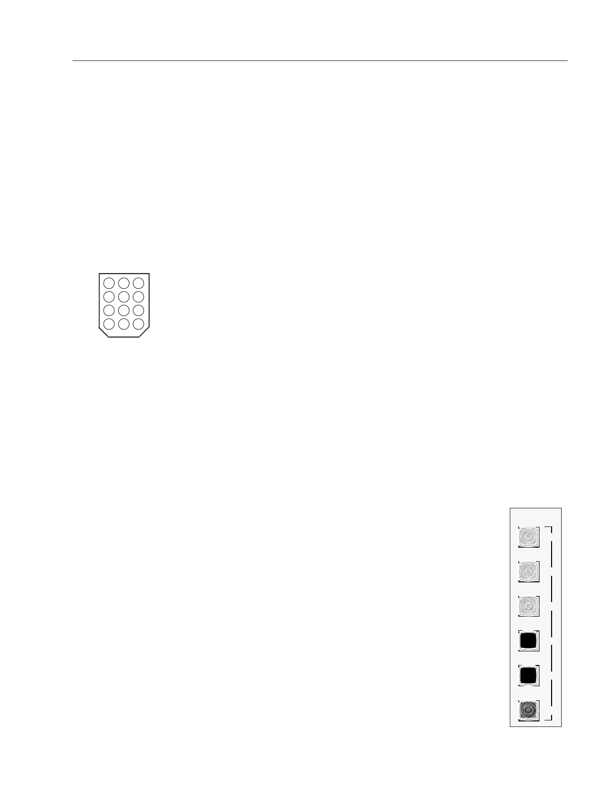
Key diagram showing back of
typical 12-pin I/O connector
plug, with pin numbers oriented
as they would be seen while
wiring. Beveled corners
correspond to PCB mounted
mating sockets.
5 46
8 79
11 1012
2 13
TA PE
PLAY
REC
STOP
REW
FF
RTZ
SW 1
SW 2
SW 3
SW 4
SW 5
SW 6
R-60 / Feb 1999
Page 3 - 14
 Loading...