-7-
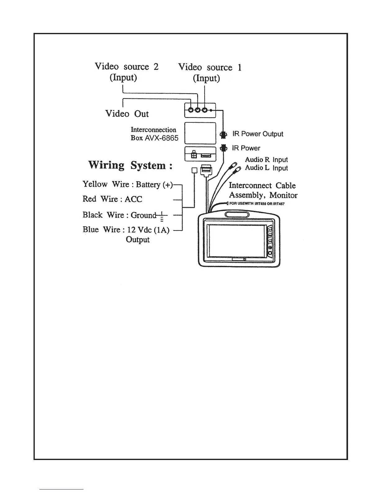
LCM500NP SYSTEM WIRING DIAGRAM
1.) Make sure the LCM500NP has been installed properly, as described in the procedures as stated on
pages 2, 3, and 5.
2.) Plug the 15 pin connector into the jack labelled -15 pin to MONITOR on the AVX-6865 Interconnection
Box.
3.) Connect the 2 pin connector to the jack labelled IR POWER output on the AVX-6865 Interconnection
Box.
4.) Connect the video source to the jack labelled VIDEO IN 1 on the AVX-6865 Interconnection Box.
5.) Connect the audio source to the 2 RCA connectors that are incorporated in the Monitor Cable
Assembly (for optional audio connection).
6.) Power Connections:
a) Red (ACC): Connect to switched 12Vdc.
b) Yellow (Batt): Connect to constant 12Vdc.
c) Blue (Remote Out): 12Vdc output.
d) Black (Ground): Connect to chassis ground.
 Loading...