AUMA MATIC Operation Instructions
AUMA Actuators, Inc. USA
Logic Board
Programming
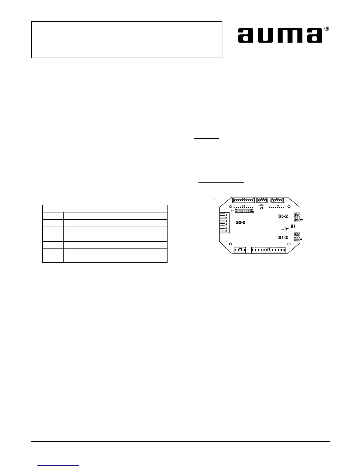
• Refer to Figure 1.
• The Logic Board has 3 sets of switches S1-2, S2-2 and S3-2.
• Switches S1-2 and S3-2 allow for either limit or torque seating in closed and open positions.
Switch S1-2
• In position 1, the actuator is set for limit seating in the clockwise direction.
• In position 2 the actuator is set for torque seating in the clockwise
direction.
Switch S3-2
• In position 1, the actuator is set for limit seating in the counterclockwise direction.
• In position 2 the actuator is set for torque seating in the counterclockwise
direction.
Switch S2-2
Switch Position S2-2 “ON”
S2.1 Remote seal in for clockwise
S2.2 Remote seal in for counter clockwise
S2.3 Local seal in for clockwise
S2.4 Local seal in for counter clockwise
S2.5 Blinker transmitter off
S2.6 Torque switch included in collective
fault signal
Also provided on the Logic Board are four solder links. When the soldered link is present on pads J1 and J3, the
integral open and close lights on the Monitor Control board within the AUMA Matic will both be on in a
intermediate valve position. When the soldered link is present on pads J2 and J4 the integral open and close
lights on the Monitor Control board will both be off in an intermediate valve position.
Figure 1
Down is on
1 2
1 2
Solder links
J1-J4
All information in this document is subject to change without notice.
ISSUE 02/02 Page 4 of 4 SE-SI-35-0001