Assembly Instruction
UniPC
+
-
BU
WH
BU
WH
BN
BU
BN
BN
S12
S3
24VDC
24VDC
BU
BN
UniPC
S12
230VAC
WH
GY
BU
BN
BK
BU
GN / YE
PE
N
L
230V AC
UniPC
BU
WH
BN
CONNETION / NAVIGATION
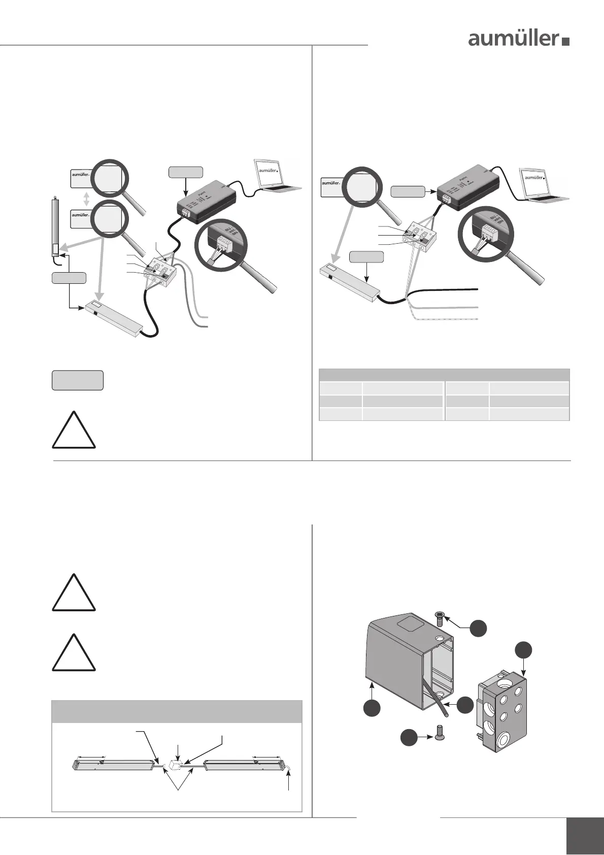
INSTALLATION STEP 2B:
C
ONNECTION OF DRIVES 230 V AC
WITH S12
I
NSTALLATION STEP 2A:
C
ONNECTION OF DRIVES 24 V DC
WITH S12 OR S3
Connect computer, Interface „ParInt“ and drives. Connect computer, Interface „ParInt“ and drives.
!
INSTALLATION STEP 2C:
C
ONNECTION OF DRIVES 230 V AC WITH S12 - PARAMETERISATION ON THE 24 V-SIDE
!
Multi-drive operating (set)
285
connection box
site-supplied
connecting „ParInt“separate drives
285
master 230V Rslave 24V L (K)
24V DC, non-halogen
ca. 3m, 3 x 0,5 mm
2
230V AC, non-halogen
ca. 3m, 6 x 0,75 mm
2
You can only con gure one drive. Separate
the drives.
For drives in multi-drive operation (set) a second cable
leads already out of the end cap. This cable can be used
for con guration with the UniPC.
Loosen the screws
(drive: type KS2).
Remove the end cap
from the drive housing
.
Pull out the cable
, strip and connect it to the
„ParInt“.
After con guring the drives, insulate the cable
.
Mounted the end cap
with screws
at the drive
housing
.
At 230V AC drives (type KS2 / KSA) with Z version use the
internal cable on the 24V-side:
3
4
1
1
2
!
Do not use an external power supply, other-
wise the drive will be destroyed.
Program without voltage. Connect only to
the „PartInt“.
3
note polarity!
24 V DC from control unit
(direction CLOSE) or
from 24 V DC switch
mode power supply
NOTE
If only one drive is programmed, an ad-
ditional power supply is not necessary.
During the parameterisation: Do not switch
off the operating voltage when connected to
a control unit, because it leads to problems.
Color DIN IEC 757
BK = black GN / YE = green / yellow
BN = brown GY = grey
BU = blue WH = white
drive
ParInt
drive
ParInt
 Loading...