B8 Left channel - (green-black)
B2 Right channel - (purple-black)
B7 Left channel + (green)
B6 Left channel - (white-black)
B4 Right channel - (gray-black)
Front speakers
Rear speakers
B1 Right channel + (purple)
B3 Right channel + (gray)
B5 Left channel + (white)
WARNING
DO NOT OPEN
5
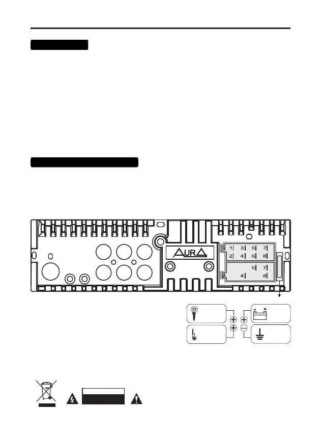
Connection
7. Connect the rest of the wires according to the diagram.
1. Make sure that the on-board voltage of your vehicle is +12 volts
2. Remove the fuse from the device before connecting the wires.
3. Connect the yellow (A4) wire to the +12 Volt DC power circuit.
4. Connect the red wire (A7) to the ACC terminal of the ignition switch.
5. Connect the black wire (A8) to the metal part of the car body.
6. Blue wire (A5) - connect to the amplifier's remote turn-on input or the antenna motor control
input
Note: Each time the yellow wire is disconnected from the 12 volt power circuit or the battery
terminal is removed, the device will revert to factory settings.
To avoid increased current consumption and unstable operation of the receiver, do not connect
the red wire (A5) to a constant +12 volt!
fuse
RED
ACC +12V
YELLOW
constant
power
+12V
BLACK
ground
MINUS
BLUE
control
wire
+12V
Mode 2 WAY (standard)
SUB - RCA subwoofer
FL - RCA front (left)
FR - RCA front (right)
RL - RCA rear (left)
RR - RCA rear (right)
ANT
MIC SWC
SUB FL RL
SUB FR RR
15 A
Mode 3 WAY (network)
SUB - RCA subwoofer
FL - RCA mid-range speaker (left)
FR - RCA mid-range speaker (right)
RL - RCA tweeter (left)
RR - RCA tweeter (right)
Connecting RCA wires
SWC - steering wheel control wired adapter input
(not included)
ANT - radio antenna connection input
(not included)
MIC - external microphone input (not included)