8
Cabling
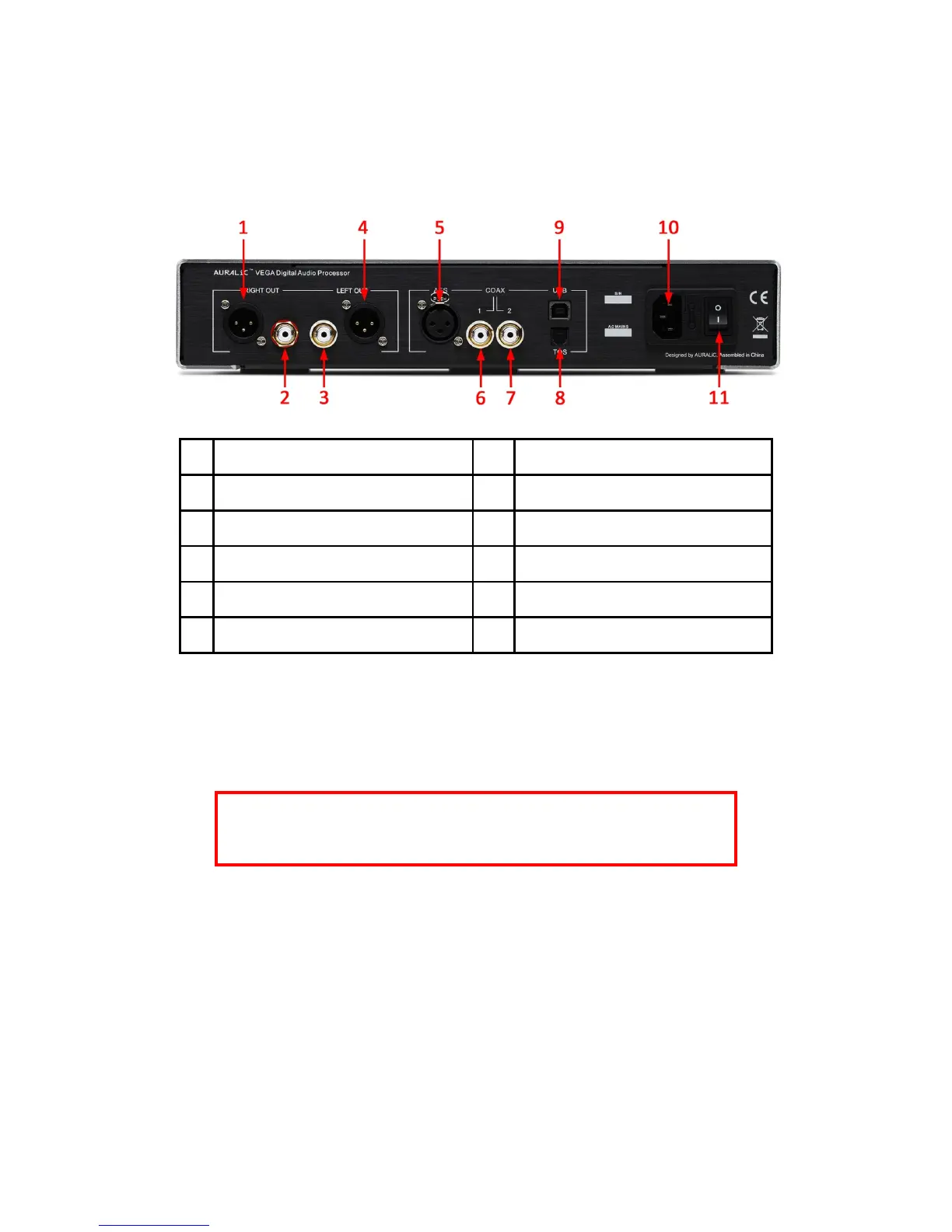
The I/O ports on the rear of the unit are shown as following:
1 Right Balanced Analog Output 7 S/PDIF Coaxial #2 Digital Input
2 Right Single-Ended Analog Output 8 S/PDIF TOSLINK Digital Input
3 Left Single-Ended Analog Output 9 USB 2.0 High Speed Input
4 Left Balanced Analog Output 10 Power Cord Socket
5 AES/EBU Balanced Digital Input 11 Power Switch
6 S/PDIF Coaxial #1 Digital Input
Please make sure to power off all units in your system before any cabling job, failed to
follow this instruction may result in permanent damage to the device and avoid any war-
ranty.
ALWAYS POWER OFF VEGA BEFORE CABLING!
Analog Outputs
The balanced and single-ended analog outputs of VEGA are individually buffered so
as to be used simultaneously, however, it is still strongly recommended to disconnect
unused ports to avoid any potential electromagnetic interference induced by cables.
The amplitude of analog outputs is adjustable with maximum level at about 4Vrms on
both XLR and RCA outputs. The output impedance of XLR output is very low at
4.7ohm so it can be used to drive almost all kinds of power amplifiers. Please pay
 Loading...