C300H / C300HI / C300H x4 / C300HI x4
C350H / C350HI / C350H x4 / C350HI x4
77
Alteration to the forklift / load relation
The relationship between the forklift and the load is altered by changes in:
- Removable attachments (see LOAD CHARTS in this manual).
- Height of the forks.
- Changes in the motion of the machine and the grade of the ground on which it is
moving.
- Smoothness and stability of the ground.
- Machine stability must be maintained while these factors change constantly
during forklift operation.
This requires careful judgement on the part of the operator.
Lifting Capacity
Machine stability is maintained only when the forklift handles loads within its rated
lifting capacity. The Load Capacity Charts are included in the section TECHNICAL
SPECIFICATIONS on this Operator’s and Safety Manual. The lifting capacity of the
machine is determined by the safe height and weight limits of the load. An overload
on the forks makes the forklift unstable, hard to handle, and will present the danger of
tipping over.
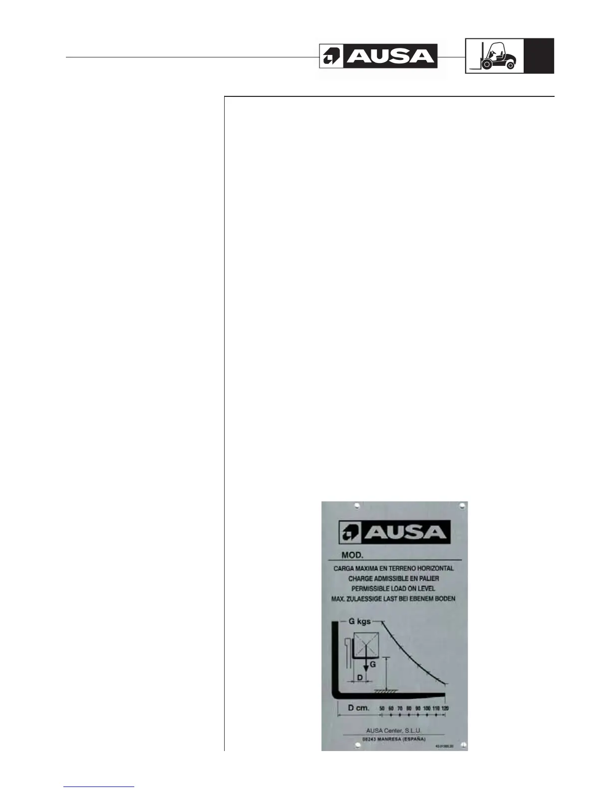
Load charts (fig. 1, 2)
The charts you can see in the section TECHNICAL SPECIFICATIONS on this
Operator’s and Safety Manual shows how much your forklift can lift as the load centre
increases out to 4in (100 mm) load center from the 20in (500 mm) or 24 in (600 mm)
(depending on models and market). Note how the lift capacity decreases as the load
centre increases. This chart is reproduced as a machine decal and is located on both
the right and the left side of the mast and at the driver seat for ease of reference during
machine operation.
The charts you can see in the section TECHNICAL SPECIFICATIONS on this
Operator’s and Safety Manual represents the load that can be lifted on a level surface,
with the load evenly displaced (like a square box with the weight centred), at certain lift
height (depending on the mast height and use) .
The horizontal axis “D” (often referred to as the “X” axis), represents the distance in
inches that the load centre is moved forward from the face of the forks.
The vertical axis “G” (often referred to as the “Y” axis), shows the load weight in pounds
o kilos.
Operating
the forklift
(fig. 1)