Do you have a question about the AUTEC C26PRO SERIES and is the answer not in the manual?
General indications, guidelines, and considerations for installing and wiring the radio remote control system.
Operator qualifications, duties, and checks before and during operation.
Actions for dangerous situations, faults, and replacement of parts.
Daily, 3-monthly, 6-monthly, and 12-monthly checks for transmitting unit, receiving unit, electrical operation, and conductors.
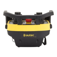
This manual provides installation, usage, and maintenance information for the radio remote control.
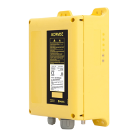
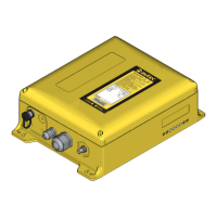
The technical data sheet details the wiring system between the receiving unit and the machine.
Procedure for powering on and starting the transmitting unit.
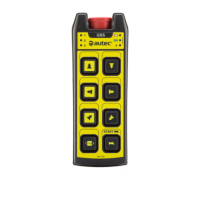
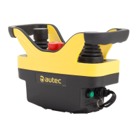
Description of key commands like Horn and STOP, and their functions.
Details on power on, start up, commands, RPM selector, speed selector, frequency change, and LED signals.
Procedures for powering off the unit and recharging the battery.
Explanation of the POWER and ENABLE lights for status indication.
Interpretation of internal LEDs indicating relay activation.
Description of the SAFETY function for protection against involuntary movements.
Description of the FLOW function related to hydraulic circuit pressure.
Explanation of the TIMED STOP command for the machine diesel motor.
Details on the function and technical data of fuses F1, F2, and F3 in the receiving unit.
Explanation of dip switches, data memory, restore pushbutton, rotary switch, and LED indicators for module setup and status.
Steps to prepare the transmitting and receiving units for calibration.
Step-by-step procedure for calibrating proportional outputs using the rotary switch and RPM selector.
Details on calibrating dither frequency, min/max values, standstill values, and auxiliary outputs.
Steps to save the calibration settings and finalize the procedure.
Explanation of automatic scan and manual selection methods for radio frequencies.
Troubleshooting guide for the transmitting unit based on LED indicators.
Troubleshooting guide for the receiving unit, checking lights, fuses, and connections.
General operating parameters, frequency, channels, range, and safety categories.
Technical details of the transmitting unit, including commands, antenna, modulation, power, and dimensions.
Technical details of the receiving unit, including power, antenna, current ratings, sensitivity, and dimensions.
| Brand | AUTEC |
|---|---|
| Model | C26PRO SERIES |
| Category | Remote Control |
| Language | English |