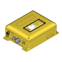
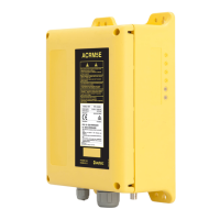
This document serves as the user's manual for the Autec Light Series Transmitter System, an industrial radio remote control designed for operating machinery from a distance. The system comprises a portable transmitting unit and a receiving unit installed on the machine.
Function Description:
The Autec Light Series industrial radio remote controls enable remote operation of machines. The transmitting unit sends coded messages via radio frequencies, each containing a unique address. The receiving unit is designed to decode messages only from its corresponding transmitting unit with the same address, preventing interference from activating system functions. In the event of disturbed, incorrect, or interrupted radio transmission, the receiving unit autonomously stops the entire system, ensuring safety. The receiving units of the Light series are equipped with a SAFETY function that protects the "machine+radio remote control" system from unintended movements when in a neutral (rest) position, even in the case of radio remote control faults. This safety feature relies on correct wiring as per the technical data sheet and proper installation.
Important Technical Specifications:
The general technical data for the Autec Light Series Transmitter System includes:
- Frequency band: 902 - 928 MHz
- Available radio channels: 32
- Hamming distance: ≥ 8
- Probability of undetected error: <10 exp-11
- Typical working range: 330 ft (100 m) (100 m)
- Command response time: ~ 100 ms
- STOP command response time: ~ 100 ms
- Passive emergency time (or passive stop): 0.35/1 sec. (This setting can be configured via DIP switch No. 1 in the receiving unit manual's "Programming" section).
- Power supply: NiMH 2.4 Vdc battery pack (LBM02MH)
- Antenna: Internal
- Output power: Meets FCC Part 15 for license-free operation
- Housing material: PA 66 (50% fg)
- Protection degree: NEMA 4 [IP65]
- Dimensions: (3.1" x 7.3" x 1.7") [(80 x 185 x 43)mm]
- Weight: 14.8 oz (420 g)
- Battery capacity with fully charged battery [at 68°F (20°C)]: ~ 12 hours
- "Low battery" warning: 3.5 min
Climatic Conditions:
- Working Temperature: Class 4K4H, -5°F to +130°F (-20°C to +55°C)
- Working Relative Humidity: Class 4K4H, 4% to 100%
- Working Air Pressure: Class 4K4H, 86 kPa to 106 kPa
- Storage Temperature: Class 1K5, -40°F to +160°F (-40°C to +70°C)
- Storage Relative Humidity: Class 1K3, 5% to 95%
- Storage Air Pressure: Class 1K4, 86 kPa to 106 kPa
- Transportation Temperature: Class 2K3, -13°F to +160°F (-25°C to +70°C)
- Transportation Relative Humidity: Class 2K3, 95%
- Transportation Air Pressure: Class 2K3, 70 kPa to 106 kPa
Usage Features:
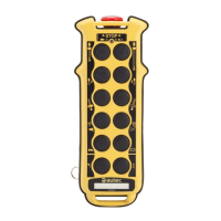
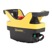
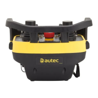
The LK transmitting unit can be used with various receiving units, including Type R102, R202, R302, and R402.
- Components: The transmitting unit features a starting keyswitch, START pushbutton, signalling LED, pushbuttons for commands, an optional selector, a STOP pushbutton, a technical data plate, a battery, and an identification plate within the battery housing.
- Power On and Start Up: To switch on, insert the starting keyswitch. To start radio remote control functions, press the START pushbutton for 1-2 seconds. A green signalling LED will light up after starting.
- Command Activation: Activate pushbuttons and/or selectors corresponding to the desired movement or selection commands.
- STOP Function: The STOP pushbutton is crucial for immediate machine shutdown in dangerous conditions. To stop, press the button. To restart, turn the STOP pushbutton in the indicated direction to deactivate it, then repeat the start-up procedure after ensuring safe working conditions.
- Battery Recharge: When the battery is low, insert it into the battery charger (operating temperature +41°F to 113°F / +5°C to +45°C). The "CHARGE" pilot light will illuminate. After a maximum of 4 hours, the light switches off, indicating a full charge.
- Switching Off: The transmitting unit should be switched off by extracting the starting keyswitch when work is stopped. The key should be kept in a safe place. The unit can also switch off automatically if the battery is low or if inactive for more than 3.5 minutes (configurable via programming).
- Signalling LED:
- Slow blinking: Indicates normal working mode.
- Fast blinking: Indicates low battery. The unit will switch off 3.5 minutes after the LED starts blinking. Action: Switch off the unit and replace the battery.
- Steady light (on starting): Indicates one or more actuators and/or the STOP pushbutton are activated. Action: Release all actuators and/or the STOP pushbutton. (Note: This LED is red if present).
- Frequencies: The system operates within frequency bands permitted by European regulations. It can be programmed for AUTOMATIC scan mode (default) or MANUAL selection mode.
- Manual Selection Mode: Allows operation at a specific frequency set manually via DIP switches in the radio modules. Requires authorized Autec personnel for setup or modification.
- Automatic Scan Mode: Allows changing the working frequency without internal interventions on the transmitting or receiving unit. To change frequency:
- With the transmitting unit started (blinking green LED), press and hold the START pushbutton (a), then press the STOP pushbutton (b), and finally release the START pushbutton.
- Unlock the STOP pushbutton by turning it as shown in the photo, and repeat the starting procedure. During this process, the receiving unit temporarily loses radio link; keep the START pushbutton pressed for 8-10 seconds for reconnection.
- Programming (E16STXUS1 Transmitting Module): Programming of DIP switches must be done with the battery removed and only by authorized personnel. Incorrect closure can compromise the unit's seal. For correct functioning, the group of 8 DIP switches (excluding DIP 1) on both the transmitting (E16STXUS1) and receiving (E16SRXUS1) radio modules must be set identically. The programming of the other group of four DIP switches must never be modified.
- DIP 1 (ON): Transmitting unit never switches off automatically.
- DIP 1 (OFF): Transmitting unit switches off after approx. 3.5 minutes if no movement commands are entered.
- DIP 2 (ON): Deactivation of low battery warning from horn on machine.
- DIP 2 (OFF): Activation of low battery warning from horn on machine.
- DIP 3 (ON, if DIP 8 is OFF): Automatic scan of frequencies in the 915-928 MHz band.
- DIP 3 (OFF, if DIP 8 is OFF): Automatic scan of frequencies in the 902-915 MHz band.
- DIP 3-7 (ON/OFF, if DIP 8 is ON): Manual selection mode of frequencies using DIP 3-DIP 7 (refer to "Appendix: Frequency Table").
- DIP 8 (ON): Manual selection mode of frequencies using DIP 3-DIP 7.
- DIP 8 (OFF): Automatic scan mode of frequencies in the band selected by DIP 3 (DIP 4-DIP 7 indifferent).
Maintenance Features:
- General Warnings: Always ensure the battery is removed before any maintenance. All maintenance actions must be verified and recorded. Replace the battery with a charged one and ensure the starting keyswitch's efficiency before maintenance. Routine maintenance is crucial for safe operation. Always confirm that commands sent by the transmitting unit activate only the expected operations after maintenance. If irregularities are noted, the system should be taken out of service.
- Routine Maintenance (Every Three Months Recommended):
- Remove dust or other material from the transmitting unit. Do not use solvents, flammable/corrosive materials, high-pressure water, or steam cleaners.
- Store the transmitting unit in clean, dry areas.
- Ensure gaskets, bellows, and caps of actuators (selectors and pushbuttons) are intact, soft, and elastic.
- Ensure the battery housing and contacts are clean.
- Check the structural integrity of the transmitting unit.
- Ensure panel symbols are recognizable; replace the panel if necessary.
- Check that the identification plate is readable and undamaged.
- Verify the STOP pushbutton works properly before use.
- Half-Yearly Maintenance: Ensure all relay contacts of the receiving unit operate correctly; check that contacts close when a maneuver is enabled and open when disabled.
- Special Maintenance (Autec Service): Any faults must be repaired by authorized Autec personnel using original Autec spare parts only. When contacting the Authorized Service Center, provide the serial number, purchase date, problem description, device location (with contact person), and local supplier for faster service.
- Disposal: Dispose of the radio remote control through waste separate collecting services in the user's country. Pay particular attention to battery recycling according to local rules; do not dispose of batteries with domestic trash.