Do you have a question about the AUTEC Dynamic Plus Series and is the answer not in the manual?
Details the overall structure of the Autec Dynamic Plus series Radio Remote Control manual, including its various parts.
Defines key terms and explains captions used throughout the manual for clarity and understanding.
Explains symbols used in the manual, highlighting important information and safety-related warnings.
Covers guidelines for instruction storage and intellectual property restrictions related to the manual.
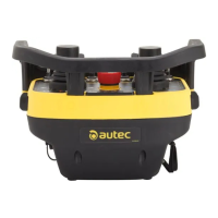
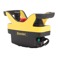
Introduces the DJR Transmitting Unit as part of the Autec Dynamic Plus series and its application on machines.
Details conformity of Radio Remote Controls with standards and working requirements in various countries.
Provides contact details for Autec, distributors, and service centers, including warranty and technical assistance.
Identifies and labels the various components and connection points on the DJR Transmitting Unit.
Maps labels (A-P) to specific components like displays, LEDs, buttons, and connectors on the unit.
Details power supply, antenna, housing, protection degree, dimensions, weight, and run times.
Explains the purpose and requirement of the Technical Data Sheet for correct wiring and record-keeping.
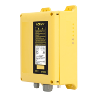
Details the types of plates on the DJR Transmitting Unit and the information they contain (serial number, ID, etc.).
Explains the meaning of green and red LEDs and 'Data Feedback' LEDs for operational status and malfunctions.
Details the conditions triggering acoustic signals and their relation to red LED indicators and malfunctions.
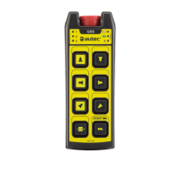
Covers power keyswitch usage, START/STOP button functions for machine control and safety.
Details interaction with 2.7"/4.3" displays and the meaning of various control commands and switches.
Explains the low power function and procedures for battery insertion and removal for the transmitting unit.
Details procedures for removing the battery and the function of the 'ID internal tx memory' key.
Guides on starting the radio remote control, monitored commands, and activating specific commands.
Explains actions for radio link interruptions, automatic unit switch-off conditions, and low battery alerts.
Covers procedures for switching off the unit and using the 'Data Feedback' function for machine status.
Details cable control usage, safety precautions, and procedures for using a backup unit.
Covers usage restrictions, especially regarding electronic devices, and required user behavior and responsibilities.
Details the assembly and correct use of the waist belt or shoulder harness for the transmitting unit.
Directs users to Part A of the manual for detailed instructions on correct radio remote control maintenance.
Lists malfunctions signaled by red and green LEDs, their possible causes, and recommended solutions.
Details malfunctions displayed on the 2.7" screen, including descriptions, causes, and troubleshooting steps.
Explains how to identify activated commands using LED blink patterns and correlating them with specific functions.
Refers users to Part A of the manual for correct procedures regarding decommissioning and disposal of radio remote controls.
| Operating Temperature | -20°C to +55°C |
|---|---|
| Enclosure Protection | IP65 |
| Transmission Range | up to 100m |
| Power Supply | Battery |
| Protection Class | II |
| Dimensions | varies by model |
| Weight | varies by model |